What is thermistor? How it is used in Wheatstone Bridge?
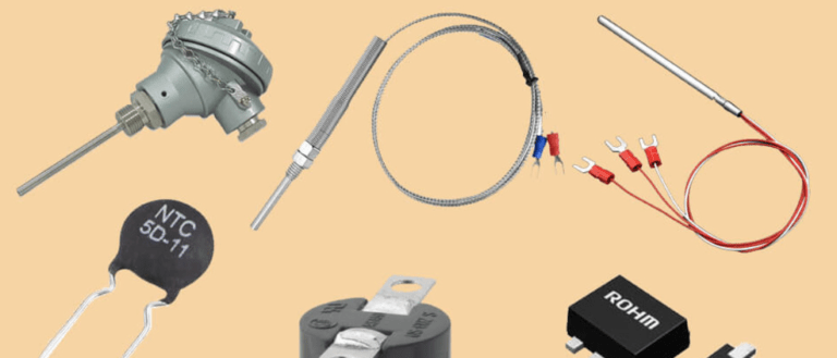
What is thermistor: It is a passive temperature transducer so battery must be used in its circuit. Thus a thermistor is a transducer which changes its resistance due to change in temperature.

What is thermistor: It is a passive temperature transducer so battery must be used in its circuit. Thus a thermistor is a transducer which changes its resistance due to change in temperature.

Before discussing about what is transducer, first we shall see basic difference between sensor and a transducer. They both are used to sense a change within the environment they are surrounded by or an object they are attached to. However, a sensor will give an output in the same format and a transducer will convert the measurement into an electrical signal.
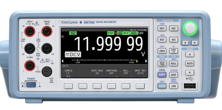
To understand how digital multimeter works, let us see the block diagram of DMM is given below. The working of each block to measure different types of electrical quantities is explained.
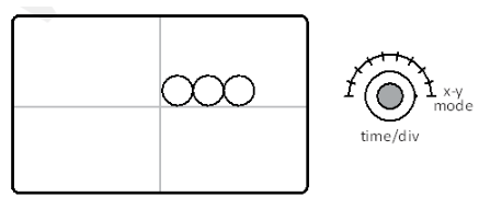
To measure the phase different between two waveforms, their frequencies must be same. Connect the two waveforms randomly at x-input and y-input of CRO. Keep time/div knob in x-y mode. Now a Lissajou’s pattern of an ellipse is obtained.
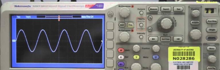
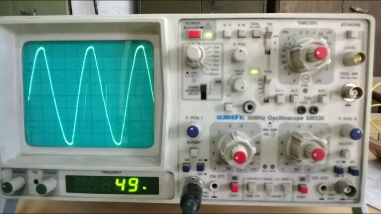
The CRO is a versatile laboratory instrument. It is used for all types of measurements like AC/DC voltage, AC/DC current, frequency and phase measurements. These methods are explained in details with practice exercise.
The working of block diagram of CRO is given here. The separate working of time base generator is also explained in details of intrinsic stand off ratio.
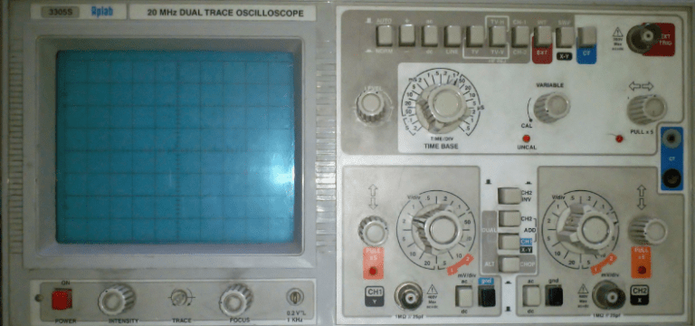
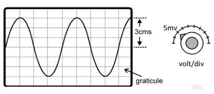
The instrument of CRO is fitted with number of controls on its front panel and the back panel along with the screen of CRT. These are different types of rotating knobs which are actually variable resistors to control voltages inside the CRO circuit.

What is fluorescence, Phosphorescence & Persistence in terms of CRT? Complete article with correct definitions and details...
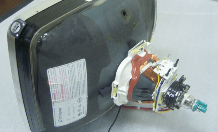
Let us see How deflection system in CRT work? Explain with diagram - The electron beam can be deflected using electric or magnetic field. As per the application of CRT, there are two types of deflection systems used in CRT – the electrostatic deflection system and the magnetic deflection system.
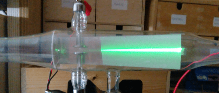
Let us see what is Cathode Ray Tube (CRT)? Explain with diagram CRT. The cathode ray tube is the most important part in CRO. It is made up of thick glass (with vacuum inside) and it is shaped like a funnel. There are number different electrodes inside the CRT.
In previous circuit of Hartley oscillator, we used two coils L1 and L2 and one capacitor C. But in this circuit of Colpitt’s oscillator, we use two capacitors C1 and C2 with a single coil L. Let us discuss about this circuit.
In Hartley Oscillator, the combination of L-C is used to produce high output frequency. It consists of one transistor, a tank circuit and the positive feedback to produce oscillations. Its circuit diagram is given below.
In LC oscillators, combination of inductor (L) i.e. coil and capacitor (C) are used. When we connect inductor (L) in parallel with capacitor (C), this combination is called tank circuit. We shall understand the working of tank circuit first.
The Wien Bridge Oscillator circuit is an RC oscillator which uses the basic property of Wien Bridge Circuit. It uses to stage amplifier circuit and leading-lagging RC network, as shown in the following block diagram.
The RC Phase shift oscillator uses common emitter configuration i.e. CE configuration of transistor. It produces 180° phase shift in addition to the phase shift of 180° by the transistor. So we get total 360° phase shift to produce positive feedback.
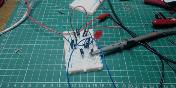
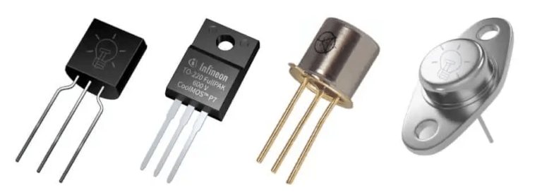
An electronic oscillator is a circuit which can produce alternating voltage i.e. AC voltage from DC voltage like battery. It consists of semiconductor devices like transistor, MOSFET, etc.
UJT has one PN junction with two internal resistances Rb1 and Rb2 such that Rb1 is the internal resistance between base-1 and emitter. And Rb2 is the internal resistance between base-2 and emitter.
A Metal oxide semiconductor field effect transistor (MOSFET) is also known as the IGFET i.e. insulated gate FET. The schematic constructional diagrams of both n-channel and p-channel MOSFETs are given below.
The Junction Field Effect Transistor consists of one long n-channel with two p-layers inserted at the sides. The n-channel forms the conducting path for the charges.
The small input voltage Vin is amplified by the transistor and we get output voltage Vo across emitter resistor of the transistor. In this configuration, when input signal is positive going, output is also positive and when input is negative output is also negative, as shown in above wave diagram.