- What is Cathode Ray Tube (CRT)? Explain with diagram
- How deflection system in CRT work? Explain with diagram
- What is fluorescence Phosphorescence & Persistence in terms of CRT?
- How the circuit of CRO works? Explain working of each block with block diagram
- How to use the front panel controls of Cathode Ray Oscilloscope?
- How to measure AC/DC voltage & current using CRO? Explain with diagrams
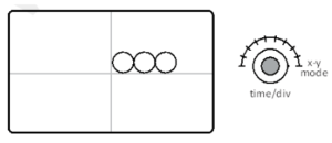
- How to measure frequency & phase using Lissajou’s patterns on CRO? Explain with diagrams
- How digital multimeter works? Explain with diagram
Introduction to CRT
The Cathode Ray Tube (CRT) is a fundamental electronic component, most notably used in devices like cathode ray oscilloscopes (CROs) and older television sets. It is a vacuum tube that contains an electron gun and a phosphorescent screen and operates based on the principle of cathodoluminescence. Its ability to control electron beams precisely makes it versatile in displaying images, waveforms, and measurements in real time. CRTs have significantly contributed to advancements in science, technology, and entertainment.
Who Invented the CRT?
The invention of the CRT traces back to the work of German physicist Karl Ferdinand Braun in 1897. Braun introduced the first cathode-ray oscilloscope, which incorporated a CRT to visualize electrical signals. However, the groundwork for cathode rays and their applications began earlier, with Sir William Crookes, who developed the Crookes tube—a precursor to the CRT. Braun’s pioneering work in CRT technology earned him recognition and laid the foundation for modern display and measurement systems.
Basic Principle of CRT
The CRT operates on the principle of electron emission, acceleration, and deflection:
- Electron Emission: A heated cathode emits electrons through thermionic emission.
- Acceleration: These electrons are accelerated by high positive voltages applied to a series of anodes.
- Deflection: The electron beam is directed and controlled using deflection plates, which modify its trajectory based on electrical signals.
- Display: The focused beam strikes a phosphor-coated screen, causing it to glow at the point of impact, thus creating visual patterns or waveforms.
Internal Components of a CRT
The CRT comprises various key components:
- Connecting Pins: Interface for connecting internal electrodes to external circuits.
- Sealing Base: Ensures a vacuum inside the tube.
- Filament and Cathode: Generate the electron beam.
- Control Grid: Regulates electron flow and beam intensity.
- Anodes: Accelerate and focus the electron beam.
- Deflection Plates: Control beam movement along x and y axes.
- Aquadag Coating: Absorbs reflected electrons to prevent interference.
- Screen: Displays the electron beam’s impact as a luminous spot.
- Graticule: Measurement reference grid for accurate readings.
Types of CRTs
CRTs can be classified into the following types based on their application and construction.
- Electrostatic Deflection CRT: Commonly used in CROs. Deflection is achieved by applying voltages to vertical and horizontal deflection plates.
- Electromagnetic Deflection CRT: Used in television sets and radar displays. The electron beam is controlled by magnetic fields generated by coils.
- Storage CRT: Capable of retaining images for extended periods. Useful in data visualization and analysis.
- Color CRT: Found in older television and computer monitors. Utilizes three electron guns (red, green, blue) to create a full spectrum of colors on the screen.
The cathode ray oscilloscope is a versatile laboratory instrument. If a laboratory has only CRO in it, other measuring instruments may not be required. Using CRO, we can very accurately measure, AC/DC voltage, AC/DC current, resistance, phase and phase difference between two or more waveforms, relative frequency of a waveform, observe the amount of noise present on a signal, etc. In addition, CRO is also useful to observe the shape of waveform or signal and observe its real time progression on time axis.
Cathode Ray Tube (CRT)
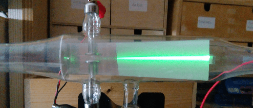
CRT i.e. cathode ray tube is the most important part in CRO. It is made up of thick glass (with vacuum inside) and it is shaped like a funnel. There are number different electrodes inside the CRT.
The working of each electrode is given below. The description of each electrode from left to right of the CRT is given below –
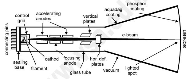
- Connecting pins: These pins are internally connected to different electrodes inside the CRT.
- Sealing base: After fitting all electrodes in CRT, vacuum is created in it and then it is sealed.
- Filament: The filament is used to heat up the cathode fitted on it indirectly. It is made up of resistive material like tungsten. It is connected to 6.3V AC.
- Cathode: It is used as the source of free electrons to produce electron beam. It is cylindrical in shape and made up of thick copper, closed at one end. It is connected high negative voltage (>20kV DC).
- Control grid: It covers the cathode. It is made up of thick copper. It is used to control the number of electrons in electron beam. The cathode is connected to variable negative voltage. It has tiny hole at the center. The electrons emitted from cathode come out from this hole. When electrons come out, they get diverged due to mutual repulsion.
- The three anodes: They are used to accelerate and focus the cathode electrons on screen. All the three anodes are hollow cylinders and fitted coaxially. They are connected to high positive voltage in decreasing order from left to right (approximately 80kV, 60kV and 40kV DC respectively).
- Deflection plates: There are four deflection plates i.e. two pairs: vertical deflection plates to deflect electron beam on screen, along y-axis and the horizontal deflection plates to deflect it along x-axis.
- Aquadag coating: It absorbs all the electrons bounced back from screen after striking on the screen. It is a thin metallic coating applied on funnel shape of CRT from inside. It is internally connected to last accelerating anode.
- Screen: The screen displays waveforms and patterns drawn on it, by the electron beam. It is coated with phosphor compound, from inside. When high speed electron beam strikes on it, the phosphor absorbs K.E. of electrons and emits photons from that point, where the beam strikes.
- Graticule: It is the measurement scale (or reference scale) of 1cm x 1cm printed on the screen from front side. It is used to measure the displacement of electron beam on screen and to calculate different parameters of waves and patterns. This scale is used with volt/div and time/div scale values.
Applications of CRT
- Oscilloscopes: For analyzing and measuring electrical signals.
- Televisions and Monitors: For visual display purposes.
- Radar Displays: For tracking and navigation.
- Gaming Consoles and Arcade Machines: Early versions relied on CRT technology for rendering graphics.
Selected Videos for better study
How Cathode Ray Tubes Work
This video offers a comprehensive overview of the working principles behind CRTs, detailing the electron emission and deflection processes.
Understanding CRT Oscilloscope Basics
An educational video that explains how CRT oscilloscopes operate, including the role of the electron gun and deflection plates in signal visualization.