- What is Cathode Ray Tube (CRT)? Explain with diagram
- How deflection system in CRT work? Explain with diagram
- What is fluorescence Phosphorescence & Persistence in terms of CRT?
- How the circuit of CRO works? Explain working of each block with block diagram
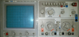
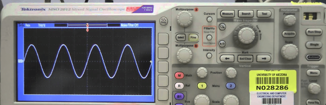
- How to use the front panel controls of Cathode Ray Oscilloscope?
- How to measure AC/DC voltage & current using CRO? Explain with diagrams
- How to measure frequency & phase using Lissajou’s patterns on CRO? Explain with diagrams
- How digital multimeter works? Explain with diagram
Block diagram of CRO
The working of CRO can be understood by dividing the complete circuit into two main parts: the vertical section and the horizontal section.
Vertical Section
Y-input: This is main input of CRO. The signal, which we want to observe, is connected to this input.
Vertical attenuator: It consists of RC voltage divider. This circuit protects the CRO circuit from dangerously high input voltage. However, if the input voltage is weak then attenuator does not reduce it, but feeds it to the amplifier circuit.
Vertical amplifier: It is a set of preamplifier and power amplifier circuits. The gain of amplifier can be controlled by adjusting Volt/div knob.
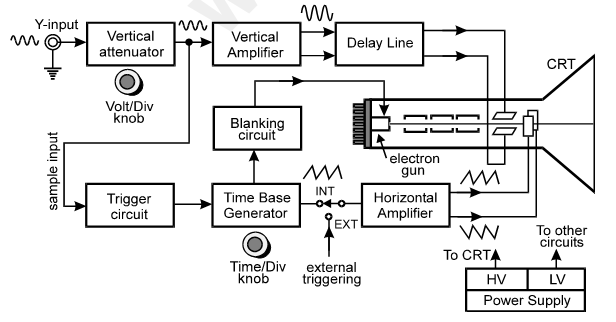
(waveforms shown at each point in the diagram are very important)
Delay line: The delay line creates a small amount of delay, so that the signal of y-input and the sawtooth signal both will appear on vertical and horizontal deflection plates, simultaneously. This delay is very small about 0.25µsec.
Horizontal Section
Trigger circuit: It takes the sample from the vertical attenuator output and feeds it to time base generator (sawtooth oscillator). So the TBG starts only when there is signal at y-input.
Time base generator: It is a sawtooth oscillator circuit (UJT Oscillator). The sawtooth wave is used to deflect the electron beam horizontally. Its frequency is controlled by Time/div control knob. The output of TBG is fed to horizontal amplifier, through INT/EXT switch.
When the switch is in INT position, the output of TBG is connected to horizontal amplifier. When the switch is in EXT position, sawtooth wave is cut off and external signal can be connected to CRO through x-input.
Horizontal amplifier: It is a high voltage amplifier with phase inverter circuit. It has two outputs: One output produces positive sawtooth wave and other produces negative sawtooth wave. The first output is connected to right side HD-plate and the second output is connected to left side HD-plate. So the two plates are at equal magnitude of voltage with opposite polarity.
Blanking circuit: It is necessary to suppress the retrace of electron beam when it is coming back from right to left of the screen. The retrace may create confusion with the original wave. So when the electron beam reaches right end of screen, the blanking circuit produces high negative voltage bias on control grid to stop electron beam, temporarily.
HV/LV power supply: The high voltage section is used to power different electrodes of CRT and the low voltage section is used to power the semiconductor circuits of the CRO.
Internal circuit of TBG
Working: The circuit diagram of UJT oscillator used in TBG block is given below. When CRO is switched the circuit remains inactive, unless it receives trigger pulse from trigger circuit.
When trigger pulse is received, the capacitor C starts charging through resistor R i.e. Time/div control knob. Now voltage across C increases slowly i.e. we get the rising edge (see waveform below). The rising edge time is known as sweeping time of the beam. During this time, the beam deflects from left to right of the screen.
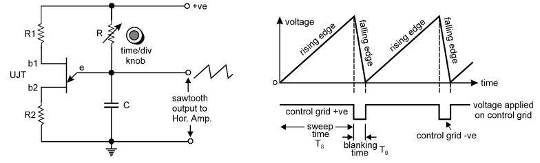
When the rising edge reaches at peak value the UJT triggers and it discharges capacitor C quickly. Due to this we get falling edge. The falling edge time is called blanking time, during which the beam is blanked. The value of peak voltage Vp of sawtooth wave is given by –
Vp = η.(Vbb + 0.6)
Where, η = Rb1 / (Rb1+Rb2)
Conceptual Study Questions (Think on it!)
- What will happen if we do not use Aquadag coating in CRT?
- Why there is a large potential difference between the anodes inside the CRT?
- Why the electron beam is not absorbed by the anodes and deflection plates?
- Why distortion is produced when we convert sine wave into triangular wave?
- What will happen if we do not connect any signal to both vertical and horizontal deflection plates of CRT?
- Why the screen of CRT has longer horizontal length than vertical height? Why such aspect ratio is maintained in TV also?