The transistor is used as an amplifier. But in amplifier circuit there two input terminals and two output terminals. However, the transistor has only three terminals. So any one terminal of the transistor is KEPT COMMON to the input and output terminals of amplifier circuit. Thus there are three possible configurations of transistor, common base (CB), common emitter (CE) and common collector (CC) configurations.
Typical Circuit
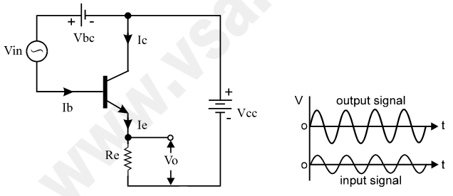
The circuit of common collector configuration or amplifier is shown below. It is also known as emitter follower circuit. In this circuit, the emitter is common to both input and output terminals of amplifier circuit. Thus, the input signal is connected between base & emitter and the amplified output signal is taken between collector & emitter, so that emitter is common.
Mathematical Analysis
The small input voltage Vin is amplified by the transistor and we get output voltage Vo across emitter resistor of the transistor. In this configuration, when input signal is positive going, output is also positive and when input is negative output is also negative, as shown in above wave diagram. So the input and output signals are IN PHASE i.e. input and output have 0° phase difference between them. Hence the circuit is called as non-inverting amplifier circuit.
In this circuit, input current is Ib and output current is Ie. So the current gain of the circuit is the ratio of collector current to its base current.
Current gain = Ie / Ib since Ie > Ib so current gain is large
Input resistance = Vin / Ib as Ib is very small, input resistance is very high
Output resistance = Vo / Ie as Ie is very large, output resistance is low
Hence finally we have –
Voltage gain = Vo / Vin = ( Ie × Re ) / ( Ib × Rb )
Exercise
- Calculate the output voltage of CC amplifier, if emitter current is 20mA and value of emitter resistor is equal to 100Ω. (Ans: 2V)
- Calculate the current amplification factor (β) of the transistor used in CC amplifier, if base current is 10uA, output voltage is 500mV with emitter resistor of 10kW. (Ans: β = 4)
- Determine the voltage gain, input resistance and output resistance of the CC amplifier circuit if input and output voltages are 200uV and 5mV with base and emitter currents as 10uA and 15mA. Also calculate the current amplification factor of the transistor.
(Ans: 25, 20Ω, 0.33Ω, β = 1499)
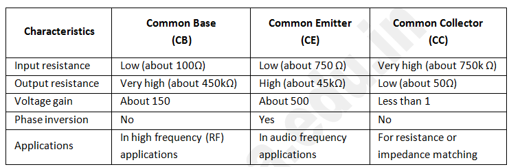
CB, CE and CC Comparison