Definition: An electronic oscillator is a circuit which can produce alternating voltage i.e. AC voltage from DC voltage like battery. It consists of semiconductor devices like transistor, MOSFET, etc.
The oscillators are widely used in industrial and communication electronics. They can produce different types of waveforms like sine wave, triangular wave, saw-tooth wave, square wave, etc.
Before reading about oscillators, I suggest you to read the article Faraday’s Laws of Electromagnetic Induction.
Important Definitions
Wave: A wave is defined as electrical variation either generally in voltage or in current, with respect to time. There are two types of waves: regular wave and irregular wave.
A regular wave has two parts: the positive half and the negative half cycles. The time length of one positive and consecutive negative half cycle, produces one complete cycle. The time length of one complete cycle is called as wavelength. Its unit is meter (m).
Phase: The phase is defined as the distance between starting point of a wave and origin. It is measured in degrees. Always remember that when the phase of two waves is 180° out of phase with respect to each other, they cancel out.
Frequency: The frequency is defined as the number of cycles per second. Its unit is Hertz (Hz).
Amplitude: Amplitude is defined as the height of peak point of the wave from x-axis. It is measured in Volts (V).
Tank circuit: It is the combination of a coil and a capacitor. It can produce electrical oscillations, known as damped oscillations.
Amplifier: It is an electronics circuit, which increases the amplitude of weak signal. Its gain is always greater than one.
Gain: It is defined as the ratio of output to the input of an amplifier.
Noise: Noise is defined as any unwanted (but unavoidable) electrical disturbance. There are many types of noises: the thermal noise (produced due to thermal vibration of electrons), white noise (produced in semiconductors), RF noise (produced due to radio frequency disturbances), cosmic noise (produced due to cosmic radiations) and a large number of others.
Classification of Oscillators
The general purpose classification of oscillators is give below:
- As per the type of waveform an oscillator circuit generates, there are two types of oscillators: Sinusoidal and non-sinusoidal oscillator.
- As per the type of feedback used in an oscillator, there are two types of oscillators: positive feedback type oscillator and the negative feedback type oscillator.
- Lastly as per the type of components used in the oscillator, there are three types of oscillators: LC oscillator, RC oscillator and crystal oscillator.
Requirements of Oscillator
To design an oscillator circuit, it must contain –
- An amplifier: To amplify the signal properly and faithfully.
- Positive feedback: The oscillator circuit must contain a positive feedback to create oscillations.
- Amplitude limiting device: When there is positive feedback, due to regeneration, the amplitude of the signal will go into saturation. So to avoid this, there must be an amplitude limiting device, in an oscillator circuit.
- Frequency control circuit: There must be a frequency control network in order to control the output frequency as per the user’s need.
Barkhausen Criterion
Definition
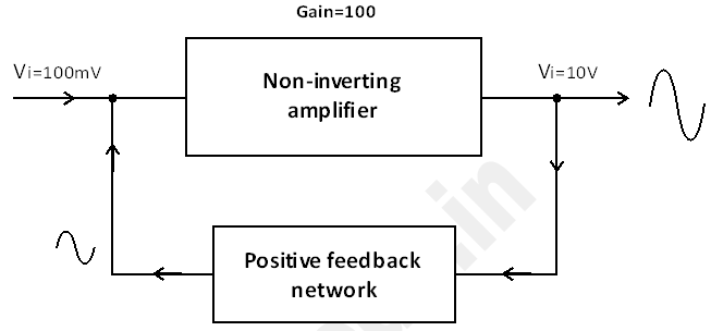
Any oscillator circuit must use an amplifier whose gain should be greater than unity i.e. gain > 1. Also the oscillator circuit must use a positive feedback to create oscillations. The block diagram of general purpose oscillator is given below.
The Amplifier
The amplifier used in oscillator is known as non-inverting amplifier. This type of amplifier produces output signal which is in-phase with its input signal. The gain of such amplifier is greater than one.
Positive Feedback
To produce oscillations, the oscillator circuit must contain positive feedback. Since the input-output of the amplifier are in phase, if we connect fraction of output of amplifier back to input, it is called positive feedback.
Amplitude Limiting Device: The action of amplitude limiting is done inside the amplifier and the feedback network.
Frequency Control Circuit: The frequency control of an oscillator is decided by the combination of either LC or RC components used in the circuit. The formulas to calculate the output frequency of oscillator circuit are given below:
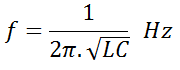
For LC type Oscillator circuits the formula is given by –
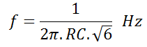
For RC type Oscillator circuits the formula is given by –
In next part…
In next part of this series, we shall see the types of oscillators. There are different types of oscillator circuits depending on its working principle and the types of components used in it.