- Introduction to Electronic Oscillators
- How Tank or Resonant Circuit Works?
- How RC Phase Shift Oscillator works? Complete working with circuit
- How Wien Bridge Oscillator works? Complete working with circuit
- How Colpitt’s Oscillator circuit works?
- How Hartley Oscillator Circuit works?
Basic Principle: The Wien Bridge Oscillator circuit is an RC oscillator which uses the basic property of Wien Bridge network. It uses to stage amplifier circuit and leading-lagging RC network, as shown in the following block diagram.
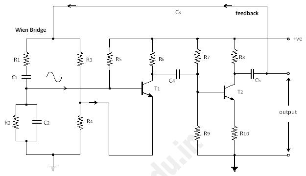
Working: In Wien Bridge Oscillator circuit, both positive and negative feedback are used. The Wien Bridge is formed by R1, C1, R2, C2, R3 and R4. There are two amplifiers used in the circuit.
In two stage amplification, the output of Amplifier-1 is out-of-phase with respect to input from Wien Bridge Circuit. But the output of second Amplifier-2 is again in-phase with the input signal.
The output of Amplifier-2 is connected back to the Wien Bridge Circuit. The voltage across parallel combination of R2, C2, is given to the input of Amplifier-1. So it gives in-phase signal as positive feedback and voltage across R4 is the negative feedback used for stability of the amplifier.
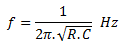
The output frequency of this circuit is given by:
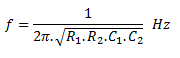
Where,
R1 & R2 = resistors in Wien Bridge circuit
C1 & C2 = capacitors in Wien Bridge circuit
If R1 = R2 = R and C1 = C2 = C then we can reduce the equation, as follows: