- Basic Concepts of Electrostatics
- How does electricity work?
- Faraday’s Laws of Electromagnetic Induction
- Ideal & Practical Voltage Sources
- Internal Resistance of Electric Source
- Ohm’s Law and Concept of AC & DC
- What is Peak, R.M.S. & Average Value of ac voltage and current
- Kirchhoff’s Current Law (KCL)
- Kirchhoff’s Voltage Law (KVL)
- Concept of Electric Power
- Concept of AC voltage – Learn in simple language
- What are the types of electric currents? Explain with diagram
So as we discussed in previous post, the electric current flows only when there is a potential difference. The unit of potential difference is Volt (V) and the unit of electric current is Ampere (A).
Definition
The Ohm’s Law states that so long as the physical state of the conductor remains the same, the amount of electric current (I) flowing through the conductor is directly proportional to the potential difference (V), provided the resistance (R) of the conductor remains the same. Mathematically, it is given as follows:
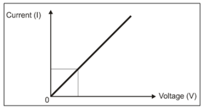
I ∝ V or V ∝ I … V/I = R = constant
i.e. R = ρ.(l/A)
Where, ρ = coefficient of resistivity of conductor
l = length of conductor
A = area of cross section of the conductor
So the practical equation of Ohm’s law is given as: V = I.R
Concept of AC & DC
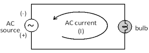
Basically there are two types of electric sources: AC and DC. We get AC source from generator and DC source from a battery or rectifier circuit. The AC source has AC voltage and AC current while the DC source has DC voltage and DC current.
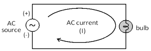
AC Voltage: It is called as alternating voltage. Its polarity always changes from (+) to (-) and (-) to (+). The frequency of AC mains voltage (i.e. domestic source of electricity board) is 50Hz.
AC Current: It is called as alternating current. Its direction always changes. Its frequency is same as AC voltage.
AC voltage is generated on the principle of Faraday’s law of electromagnetic induction. Consider a simple model of generator as shown in following figure. Suppose a rectangular coil is rotating, in anticlockwise direction, on a fixed axis within the strong magnetic field of two permanent magnets (left figure). Then AC voltage is produced across its two end points A-B. The voltage thus, produced at each position is given in the graph (right figure).
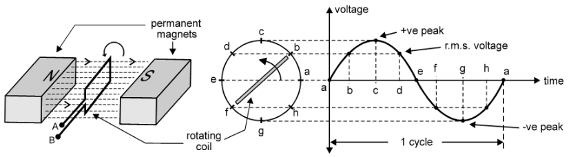
Suppose the rotation of the coil starts from point ‘a’. At point ‘a’ the coil and the magnetic field are parallel to each other. So voltage produced in the coil is zero. When coil rotates through an angle of 45°, at point ‘b’ the coil and the magnetic field are becoming perpendicular to each other. So the voltage in coil increases and attains the voltage known as r.m.s. voltage. When it comes to point ‘c’ by sweeping an angle of 90°, then it is exactly perpendicular to magnetic field. So maximum positive voltage is produced across it. In the same way, at ‘d’ the voltage is again r.m.s. voltage and at point ‘e’, its half rotation is complete and it is now parallel with the magnetic field. So again its voltage is zero. This completes positive half cycle of the AC voltage.
During next half rotation same process takes place, only negative half cycle of AC voltage is obtained. Because direction of induced e.m.f. in the coil is opposite to the previous direction. Hence, we get half cycle in IV quadrant. And lastly when the coil completes one rotation, it comes at point ‘a’ and the voltage induced in it will be zero, again.
In each case, the value of voltage generated depends on the number of turns of the coil, the strength of magnetic field and the speed at which the coil is rotating within the magnetic field.
It we rotate the magnetic field by rotating magnets, keeping the coil steady, even though same effect is observed. It means that relative motion between magnetic field and coil is necessary.
Important Points
- This AC voltage is also called as sinusoidal voltage or simply sine voltage or sine wave.
- The part of the sine wave above x-axis (i.e. in I quadrant) is called as positive half cycle.
- The maximum voltage of positive half cycle is called positive peak voltage +Vp.
- The part of the sine wave below x-axis (i.e. in IV quadrant) is called as negative half cycle.
- The maximum voltage of negative half cycle is called negative peak voltage -Vp.
- The positive peak +Vp to negative peak -Vp is called peak-to-peak voltage Vpp.
- The number of cycles per second is called as the frequency of AC voltage.
- The frequency of AC voltage which we get from Electricity Board is 50Hz.
- The average value of AC voltage is measured at 45° called as r.m.s. value –
- A sine wave is represented by the equation:
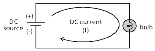
DC Voltage: It is called as direct voltage. Its polarity always remains fixed. The frequency of DC voltage is zero.
DC Current: It is called as direct current. Its direction always remains fixed. The frequency of DC current is also zero.