- Basic Concepts of Electrostatics
- How does electricity work?
- Faraday’s Laws of Electromagnetic Induction
- Ideal & Practical Voltage Sources
- Internal Resistance of Electric Source
- Ohm’s Law and Concept of AC & DC
- What is Peak, R.M.S. & Average Value of ac voltage and current
- Kirchhoff’s Current Law (KCL)
- Kirchhoff’s Voltage Law (KVL)
- Concept of Electric Power
- Concept of AC voltage – Learn in simple language
- What are the types of electric currents? Explain with diagram
Electrostatics is a branch of physics that deals with the study of electromagnetic phenomena where electric charges are at rest.
In this topic we have to study the working of capacitor in terms of electrostatics.
- Coulomb’s Law, which gives us the magnitude of the electrostatic force between two point charges.
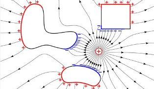
- Electric field and electric lines of force, which describe the electric field intensity (E) at a point.
- Electric field due to continuous charge distribution, which describes the electric field due to a continuous charge distribution.
- Electric field due to infinitely long charged wire, which describes the electric field due to an infinitely long charged wire.
- Electric dipole and dipole moment, which describes a pair of equal and opposite charges separated by a distance.
What is capacitance…?
Capacitance is the property of a capacitor to store electric charge when its plates are at different electrical potentials. The unit of capacitance is Farad (F).
Thus 1F is the capacitance of a capacitor between its two plates with a potential difference of 1V, when it is charged by 1C of electricity. Mathematically we show it as follows:
where, C = capacity in Farad
Q = charge in Coulomb
V = voltage across capacitor in Volts
Construction of Capacitor
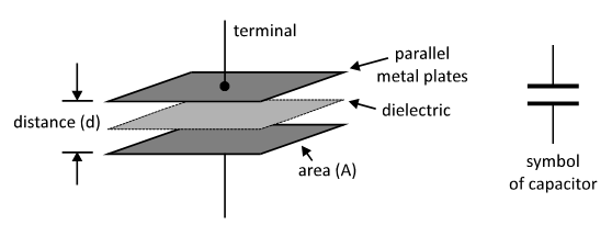
Capacitor is an electrical device which consists of two parallel metal plates separated by an insulator known as dielectric. It is used to store electric charge in the form of potential difference or voltage.
Its capacity to store electric charge is called as its capacitance. The capacity of capacitor is also given by the equation, as follows:
where, C = capacity in Farad
A = area of two plates in m2
d = distance between two plates in meter
The constructional diagram of a parallel plate capacitor is given below:
Series & Parallel Combination of Capacitors
The number of capacitors can be connected in two different styles. They can be connected in series i.e. one after another or they can be connected in parallel.
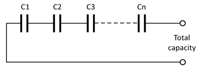
Capacitors in Series: When number of capacitor is connected in series i.e. one after another the reciprocal of total capacity is equal to the addition of reciprocals of all the capacitances.
Suppose we have number of capacitors like C1, C2, C3 …… Cn connected in series, as shown in the following circuit. Then the total capacity is given by:
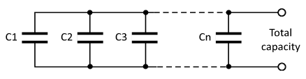
Capacitors in Parallel: When number of capacitors is connected in parallel, then their total capacitance (C) is equal to the addition of individual capacity of each capacitor.
Suppose we have number of capacitors like C1, C2, C3 …… Cn connected in parallel, as shown in the following circuit. Then the total capacitance is given by –
Charging & Discharging of Capacitor
Charging of capacitor: In following circuit, capacitor C is connected in series with a fixed resistor R, a battery and switch. When switch is ON the capacitor starts charging through the resistor.
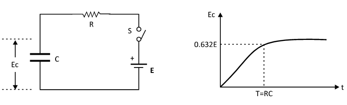
During charging, the instantaneous value of voltage across the capacitor and its time constant are given with the mathematical equation –
Where, Ec = voltage on capacitor in volts
E = battery voltage in volts
R = value of series resistance in ohm
C = capacity of capacitor in Farad
t = charging time in seconds
Discharging of capacitor: A fully charged capacitor can be discharged through a series resistor R. Suppose initially the capacitor C is charged up to a voltage . Now when it starts discharging, its voltage drops w.r.t. time. So during discharging, the instantaneous value of voltage across the capacitor and its time constant are given with the mathematical equation as follows –
Where, Ec = voltage on capacitor in volts
E = battery voltage in volts
R = value of series resistance in ohm
C = capacity of capacitor in Farad
t = charging time in seconds
Similarly during discharging Ec = 36.8% of E
Capacitive & Inductive Reactance
Capacitive Reactance (Xc): It is defined as the opposition offered by a capacitor to the flow of alternating current through it. It is given by the following equation:
Where, Xc = Capacitive reactance or opposition in ohm
f = frequency of current flowing through the capacitor in Hz
C = capacity of the capacitor in Farad
Inductive Reactance (XL): It is defined as the opposition offered by the inductor (coil) to the flow of alternating current through it. It is given by the following equation:
Where, XL = Capacitive reactance or opposition in ohm
f = frequency of current flowing through the capacitor in Hz
C = capacity of the capacitor in Farad
Real Power & Power Factor in AC supply
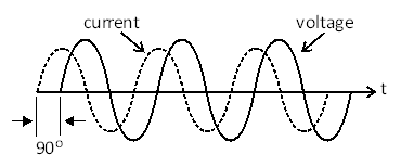
When AC supply is connected to the inductor i.e. coil, the AC voltage leads AC current by 90° as shown in the following figure. However, in practical circuits, this leading angle is slightly less than 90° due to which power is dissipated within the coil.
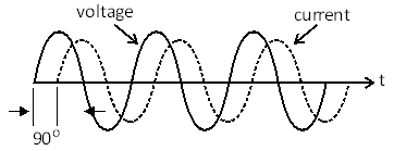
Similarly when AC supply is connected to a capacitor, the AC current leads AC voltage by 90° as shown in the following figure. But practical circuits, this leading angle is slightly less than 90°. So power is dissipated within the capacitor.
Definition of Real Power: If an AC circuit contains capacitors and coils, then the current supplied by AC source either leads or lags from the AC voltage. So the electric power is not just the product of voltage and current. It is given by:
Where, R is the total resistance in the circuit
Hence in practical AC circuits, we calculate the AC power using the following equation:
Where, φ is the ratio of pure resistance to impedance of the circuit