- Basic Concepts of Electrostatics
- How does electricity work?
- Faraday’s Laws of Electromagnetic Induction
- Ideal & Practical Voltage Sources
- Internal Resistance of Electric Source
- Ohm’s Law and Concept of AC & DC
- What is Peak, R.M.S. & Average Value of ac voltage and current
- Kirchhoff’s Current Law (KCL)
- Kirchhoff’s Voltage Law (KVL)
- Concept of Electric Power
- Concept of AC voltage – Learn in simple language
- What are the types of electric currents? Explain with diagram
The KVL is the best tool to analyse the electrical and even electronic circuits. If you learn KVL properly, you will be able to read all the branches in a circuit like we read a book with all pages in it…! So don’t ignore this topic and the topic of KCL also. It is one of the most important topic in fundamentals of electricity and electronics.
Definition
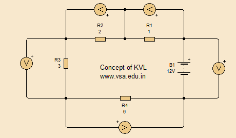
In Kirchhoff’s Voltage Law, the algebraic addition of all voltage drops in a closed circuit is always equal to zero.
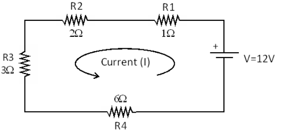
To understand the law consider the following circuit. Here a battery is connected to number of resistors like R1 = 1Ω, R2 = 2Ω, R3 = 3Ω and R4 = 6Ω with battery voltage V = 12V.
The Maths
Now if we apply Ohm’s Law, we can calculate the total current in the circuit, as follows:
Total resistance of the circuit is: 12Ω. This is because all resistors are in series.
Voltage drop across R1 is: V1 = 1A x 1Ω = 1V
Voltage drop across R2 is: V2 = 1A x 2Ω = 2V
Voltage drop across R3 is: V3 = 1A x 3Ω = 3V
Voltage drop across R4 is: V4 = 1A x 6Ω = 6V
So we can write the equation: V = V1 + V2 + V3 + V4 = 1V + 2V + 3V + 6V = 12V
That is the algebraic addition of all voltages in the circuit, including the battery voltage (V) will be equal to zero.
So the general equation of Kirchhoff’s Voltage Law is given by: