IC 555 FAQs are the collection of frequently asked questions about IC 555. Very useful to almost all types of electronics hobbyists. Many questions in this collection are never asked or never answered. We constantly update this page from the feedback that we receive from our readers.
Basic questions that are routinely asked by number of students and hobbyists are given below. We are constantly updating this page. Please contact us to ask your own question.
Why it is named so?
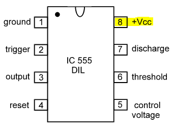
If you look at the internal block diagram of IC555 you will see that there are three resistors of 5kΩ each connected between pin-8 i.e. +ve pin and pin-1 i.e. -ve pin of the IC. These three resistors equally divide the supply voltage in three parts, 1/3 of supply voltage, 2/3 of supply voltage and 3/3 of supply voltage. The 1/3 and 2/3 of supply voltage values are very useful in the time counting of the IC. Hence the IC is named as IC555 or IC 555.
What are NE & SE Versions?
The SE version of IC 555 has large range of operating temperature, while the NE version of IC 555 is an ordinary version used in general purpose hobby circuits. The temperature ranges play a crucial role when you are using the IC for a particular application. If you want to use the IC for simple circuits, we recommend to use NE version of the IC 555.
IC 555 Calculator
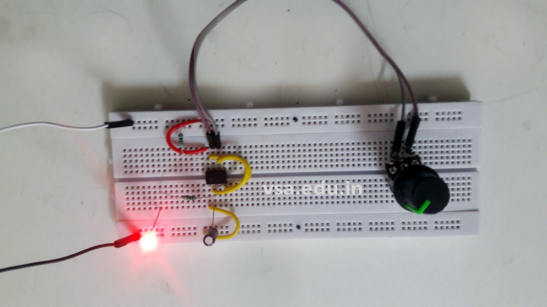
While doing experiments on IC 555, you may need to calculate the values of timing capacitor value, resistors R1 & R2 values, etc. For that you can of course use the formula given for the IC, but we suggest you to use the simple online calculator of IC 555.
Suppose you want to design a periodic timer i.e. Astable Multivibrator using IC 555, for say a time period of 1 second ON and 1 second off. It means that the frequency will be 1Hz. Then you can consider R1 = TR2 = 1kΩ and C = 1uF. You will get the value of approximate output frequency on the calculator.
How many pins are there in IC 555?
According to the manufacturer of the IC, it is available in four different packages.
- IC 555 in 8-pin dual in pin type of package
- IC 555 in 14 pin dual in pin (DIP) package that contains only one IC 555 with 14 pins. Some pins in this package are kept dummy.
- IC 556 in 14 pin dual in pin (DIP) package that contains two individual IC 555 with separate pins for each. Only the power supply pins are common to both.
- IC 555 metal CAN TO-99 package is in metal body with rounded shape, as shown below.
IC 555 Packages
There are three types of packages for IC 555 are available in the market, as shown below:
IC 555 8-pin DIP Package
Package Type
IC555 is available in 8-pin and 14-pin dual-in-line packages and also in circular TO-99 package. The TO-99 package is a metal can package with 8 metal leads.


How to use Control Voltage pin?
If you observe the block diagram of IC 555, you will see that pin-5 is connected to 2/3 voltage level and to the inverting terminal of threshold comparator. It means that this pin can be used to control the 2/3 and 1/3 voltage levels of the IC, while it is used in, say Astable Multivibrator Circuit.
Suppose we have an AMV circuit using IC 555. Its output frequency is fixed at, say 100Hz. Now if you apply a smoothly increasing and decreasing triangular wave voltage at pin-5 with respect to ground, then as the voltage of triangular wave will increase, 2/3 and 1/3 voltage values will increase. So the ON/OFF timing of the IC will change and it will affect the output frequency of the IC. For more details, check this post: IC 555 Pulse Width Modulator Circuit.
More FAQ to come…! If you have any question to ask please fill up this form and send your question. Our faculties will answer it.