
- Practical Electronics Course Kit
- TUP TUN DUG DUS – Interesting concept of universal family of transistors and diodes
In 1970s Elektor-Electronics was a famous magazine along with Electronics For You (EFY). The circuit ideas and constructional projects were the most interesting things for almost two or more decades.
The particular page photo of this article in Elektor-Electronics Magazine is still available on their website at this link.
The Elektor magazine introduced a very nice concept of using a large family of transistors (PNP or NPN) and diodes (Ge or Si) in general purpose circuits. This concept is known as TUP TUN DUG DUS. If you read it completely it will surely help you build general purpose electronic circuits.
Concept of TUP TUN DUG DUS?
The concept of TUP TUN DUG DUS was a standardization the Elecktor-Electronics magazine introduced a brand new concept of TUP TUN DUG DUS in electronics world.
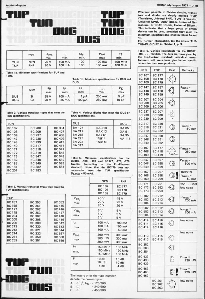
These terms are short-forms for TUP – Transistor Universal PNP, TUN – Transistor Universal NPN, DUG – Diode Universal Germanium and DUS – Diode Universal Silicon.
It means that each of these terms actually contain a wide range of semiconductor devices which are classified with systematic lab testing and checked for the standard specifications.
Real-Life Example
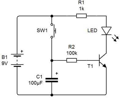
- Suppose you are using a simple transistor BC547 in a simple timer circuit.
- You started working on it and suddenly you find that BC547 is not available within your collection of transistors.
- In such case you can refer the TUP TUN DUG DUS standard library of transistors and replace the transistor BC547 with BC548, BC549, BC107, BC108, BC109, BC171, BC172, BC173 and so on…
- The only precaution that you have to take is that any other transistor that you are using in place of BC547 must meet the following parameters.
TUP & TUN – Transistor Universal PNP & NPN
The spectifications of this family are given for the general purpose use of PNP or NPN transistors in any circuits.
- Vceomax = 20V. This is the maximum value of collector-emitter voltage drop when transistor is driving a load either in collector circuit or emitter circuit.
- Icmax = 100mA. This is the maximum value of load current that the transistor can handle without damaging it.
- hfemin = 100. This means that you can use any transistor with a minimum hfe value of 100. However, if you use a higher hfe transistor then you must maintain the Vceomax and Icmax values within the prescribed limit.
- Ptotmax = 100mW. This is another parameter which you must be careful about. If you use a transistor with higher hfe, then the Ptotmax value should not exceed 100mW.
- fTmin = 100MHz. This is an important parameter if you are working with high frequency circuits like transmitter or receiver.
DUG & DUS – Diode Universal Silicon & Germanium
This family of universal diodes made up of either Germanium or Silicon can be used in any electronic circuits. The standardised parameters of these families are as follows –
DUG – Diode Universal Germanium
- VR max = 20V. This is the maximum reverse voltage that the diode can withstand without destroying itself.
- IF = 35mA. It is the maximum forward current that the diode can handle when anode is positive and cathode is negative.
- IR max = 100µA. In your circuit, if the diode in DUG family is reverse biased (anode is negative with respect to cathode), then the maximum reverse current (reverse leakage current) should not exceed 100µA.
- Ptotmax = 250mW. The maximum power that the diode can handle during forward biased condition. You can calculate it very easily, which is actually the product of forward current IF and forward voltage drop VF of the diode (0-2V to 0.3V for Germanium).
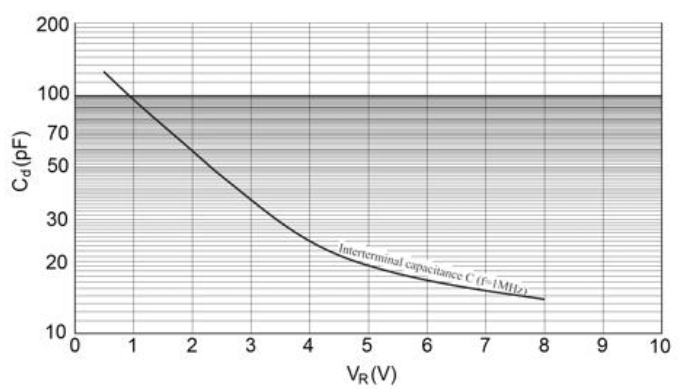
- Cd max = 10pF. It is the parameter related to the junction capacitance Cd as a function of reverse voltage VR as shown in the graph below.
It is interesting to note that the reverse current IR of Germanium diode is more as compared to Silicon diode. This is because the Germanium diode is more sensitive to temperature and hence its reverse leakage current is more. Energy gap between conduction band and valance band in case of germanium is 0.67eV but in case of silicon it is 1.1eV. As according to above discussion we can conclude that the energy required for a electron that is in valance band for germanium is lesser than silicon for jump into conduction band. So in case of germanium more number of electron present in conduction band and hence More number of holes present in valance band. And as we know reverse saturation current produces due to holes so more the number of holes in case of germanium in its valance band and more the reverse saturation current than silicon…
DUS – Diode Universal Silicon
- VR max = 25V. This is the maximum reverse voltage that the diode can withstand without destroying itself.
- IF = 100mA. It is the maximum forward current that the diode can handle when anode is positive and cathode is negative.
- IR max = 1µA. In your circuit, if the diode in DUG family is reverse biased (anode is negative with respect to cathode), then the maximum reverse current (reverse leakage current) should not exceed 1µA.
- Ptotmax = 250mW. The maximum power that the diode can handle during forward biased condition. You can calculate it very easily, which is actually the product of forward current IF and forward voltage drop VF of the diode (0-2V to 0.3V for Germanium).
- Cd max = 5pF. It is the parameter related to the junction capacitance Cd as a function of reverse voltage VR as discussed above.
List of TUP & TUN Family of Transistors
The number of transistor given in the list is practically tested in Vidyasagar Academy laboratory.
List of TUP Transistor Universal PNP
BC557, BC558, BC559, BC177, BC178, BC204, BC205, BC206, BC212, BC213, BC214, BC251, BC252, BC253, BC261, BC262, BC263, BC307, BC308, BC309 and many more within BC family.
List of TUN Transistor Universal NPN
BC547, BC548, BC549, BC107, BC108, BC109, BC171, BC172, BC173, BC182, BC183, BC184, BC207, BC208, BC209, BC237, BC238, BC239, BC582, BC583, BC584 and many more within BC family.
There are still other parameters which must be considered while selecting a particular transistor for your specific circuit. You can refer this chart for more details.
Advantages of using TUP TUN DUG DUS standards
- In general purpose electronic circuits you don’t have to be specific while selecting transistors and diodes. You can select the required component from a large family of TUP TUN DUG DUS.
- When you use a transistor in general purpose electronic circuits, the values of collector current (Ic), total power dissipation (Ptot) and collector emitter voltage (Vceo) are not that critical.
- This is because in small signal circuits the transistors are used, generally as buffer amplifier as shown in the real life example given above.


