Click here to contact us to help you construct this project under our guidance! Our expert faculty, Prof. Dattaraj Vidyasagar has guided 1000s of project for Avishkar University Level Competition, Homi Bhabha Competition, ATL Competitions, and many more….!
Introduction
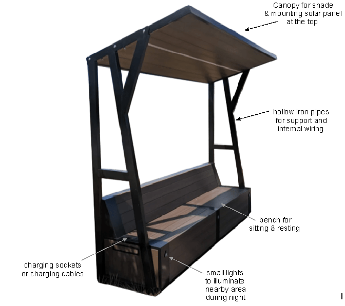
Indian climate is abundant with Solar Power. We Indians are proud of it…! The project presented here harness the Solar power with a solar panel to charge a battery and supply continuous small electric power to charge mobile phones in public places like the benches provided for resting at bus stop, garden, squares, footpaths, etc.
The project uses a simple technique to charge a high power battery continuously through solar panel output during day time and provides mobile charging facility in parallel during day time. During night, the stored electrical power in the battery takes over the mobile charging for a time span of about 10 hours after dusk i.e. the mobile phones can be charged up to 4AM next day.
Keywords
Solar panel, diodes, voltage regulator, USB-A, USB-C, Micro-USB, Lightning pins
Block Diagram
Working
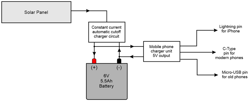
The project uses two main circuits:
The Constant Current Automatic Cutoff Charger unit: This circuit consists of a simple potential divider with voltage sensor which senses the charge on battery voltage and either starts or stops the charging process of the battery. If the battery voltage is slightly less than 6V then the charger unit sends tickle charging current to the battery and tops up its voltage up to a maximum rating of 6V.
When battery is fully charged the small leakage current continues to keep the battery voltage at topped up condition. During this time (particularly in day time), if a mobile is connected to the charger pin and the battery power is full, then the solar panel current is automatically diverted to mobile charger unit to charge the mobile phone directly on solar power and save the battery power for night.
Mobile Phone Charger Unit: This circuit consists of a reliable 3-Terminal voltage regulator IC which converts battery voltage to a constant value of 5V regardless of higher battery voltage and the voltage supplied by the solar panel simultaneously during day time.
Please note here that all the mobile phone batteries are standardized to 3.7V at their particular current rating. And to charge a battery of 3.7V the charging potential difference should be slightly higher than the battery voltage. So the output voltage of the mobile phone charger unit is kept fixed at 5V considering loading effects while charging different types of mobile phones right from old phones with micro-USB sockets to modern phones and iPhones also.
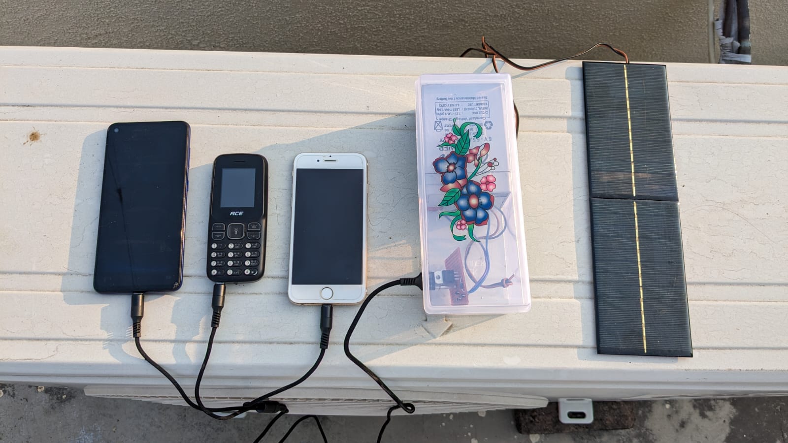
Note: The circuit is already tested with different mobile phones, iPad and with power banks also. So this is helpful for a person who wishes to charge up his power bank before starting for a journey on a train station or bus stop, etc.
Working of Solar Panel
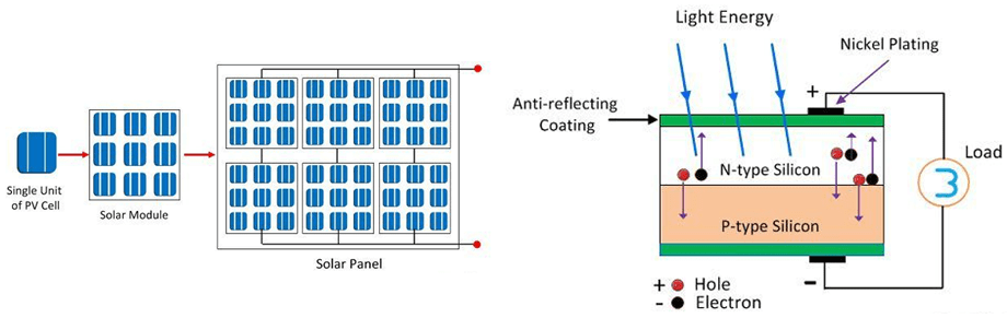
The solar panel used in my project consists of photovoltaic (PV) solar panel. When the sun shines onto a solar panel, energy from the sunlight is absorbed by the PV cells in the panel. This energy creates electrical charges that move in response to an internal electrical field in the cell, causing electricity to flow.
The Photovoltaic cell is the semiconductor device that converts the light into electrical energy. The voltage induces by the PV cell depends on the intensity of light incident on it. The name Photovoltaic is because of their voltage producing capability.
The electrons of the semiconductor material are joined together by the covalent bond. The electromagnetic radiations are made of small energy particles called photons. When the photons are incident on the semiconductor material, then the electrons become energized and starts emitting.
The energizes electron is known as the Photoelectrons. And the phenomenon of emission of electrons is known as the photoelectric effect. The working of the Photovoltaic cell depends on the photoelectric effect.
Construction of Photovoltaic Cell
The semiconductor materials like arsenide, indium, cadmium, silicon, selenium and gallium are used for making the PV cells. Mostly silicon and selenium are used for making the cell. Consider the figure below shows the constructions of the silicon photovoltaic cell. The upper surface of the cell is made of the thin layer of the p-type material so that the light can easily enter into the material. The metal rings are placed around p-type and n-type material which acts as their positive and negative output terminals respectively.
Precautions & Maintenance
- The project is almost maintenance free excluding the battery in particular.
- It is estimated that the battery life will be about 3 years from the date of installation of the unit.
- It is suggested that the solar panel must be mounted on a canopy of the public bench in slightly tilted position facing towards SOUTH to collect sufficient sunlight particularly during Winter Season.
- Since the solar panel will be mounted in tilted position and its top surface is very smooth, the deposition of dust particles on it will be minimum.
- However, regular cleaning up of the solar panel will be better to avoid slight reduction in its efficiency.
Suggested Prototype for the Project