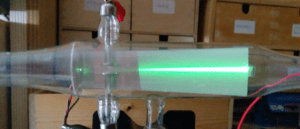
- What is Cathode Ray Tube (CRT)? Explain with diagram
- How deflection system in CRT work? Explain with diagram
- What is fluorescence Phosphorescence & Persistence in terms of CRT?
- How the circuit of CRO works? Explain working of each block with block diagram
- How to use the front panel controls of Cathode Ray Oscilloscope?
- How to measure AC/DC voltage & current using CRO? Explain with diagrams
- How to measure frequency & phase using Lissajou’s patterns on CRO? Explain with diagrams
- How digital multimeter works? Explain with diagram
Phase Measurement
We can measure the phase difference θ between two waveforms with the help of CRO. For this we want to use both input terminals i.e. y-input and x-input of CRO.
To measure the phase different between two waveforms, their frequencies must be same. Connect the two waveforms randomly at x-input and y-input of CRO. Keep time/div knob in x-y mode. Now a Lissajou’s pattern of an ellipse is obtained as shown below.

Measure the displacement “a” and “b” and then use the following equation to calculate the phase difference between two waveforms –
θ = sin-1(a/b)
Special Cases
The special cases obtained while measuring phase difference are given below –


Frequency Measurement
We can measure frequency with the help of CRO, by using two different methods. The first method is called direct method and the second method is called relative frequency measurement method.
Direct Method: In this method, the unknown frequency AC signal is connected to y-input of CRO. A waveform is obtained on the screen as shown below.

Now measure the number of divisions covered by one complete cycle of the wave. Note down the time/div knob setting. Then using the formula we can calculate the frequency –
Time (t) required for one cycle = number of div. × time/div
Unknown frequency, f = 1 / t
In above diagram, the frequency will be 10kHz.
Relative Frequency Measurement Method: We can measure the unknown frequency fx by comparing it with a known frequency value, say fy.
To measure the frequency using this method, the phase difference between the two waveforms must be zero.
Connect unknown frequency signal at x-input and known frequency signal at y-input. Keep time/div knob in x-y mode. Now a Lissajou’s pattern of loops is obtained as shown below.

Count the number of loops cut by x-axis and then y-axis and use the formula to calculate the unknown frequency fx, as follows –
fy / fx = (number of loops cut by x-axis) / (number of loops cut by y-axis)
In above example, suppose the known frequency value is fy = 300Hz, then the unknown frequency will be fx = 100Hz.
Exercise
- Calculate the phase difference between two waveforms A and B, if a Lissajou’s pattern of an ellipse is obtained on the screen, such that a = 1cm and b = 1.414cm. (Ans: 45° )
- A known frequency signal of frequency 500 Hz is connected to x-input of CRO. The unknown frequency signal is connected to y-input. A Lissajou’s pattern of an “8” is obtained on the screen. Then calculate the value of unknown frequency. (Ans: 250Hz)
- What will be the value of unknown frequency connected at x-input of CRO, if a single loop is obtained on the screen? The known frequency at y-input is 1kHz. (Ans: 1 KHz)


