LC Oscillators
In LC oscillators, combination of inductor (L) i.e. coil and capacitor (C) are used. When we connect inductor (L) in parallel with capacitor (C), this combination is called tank circuit. We shall understand the working of tank circuit first.
Tank Circuit (Resonant Circuit)
The tank circuit is also called as resonant circuit or tuned circuit. It consists of one inductor (L) in parallel with capacitor (C), as shown in the following diagram.

Fig #1: Here capacitor is charged to its peak value and the current in the circuit is zero. So the magnetic field around the coil is also zero.
Fig #2: Now the capacitor is discharging into the inductor. So magnetic field starts creating around the inductor. It takes some time to discharging to build up full magnetic field around the coil.
Fig #3: Here the capacitor is completely discharged. So voltage across capacitor is zero but full magnetic field is produced around the coil.
Fig #4: Now the magnetic field around the coil starts collapsing on the coil. Due to this, reverse current is produced and the capacitor starts charging but with reverse polarities.
Fig #5: Finally magnetic field around the coil is zero. So current is zero and capacitor is fully charged.
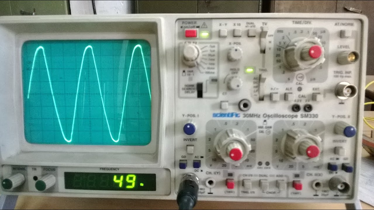
In this way, the capacitor charges and discharges in the circuit to produce pulsating magnetic field around the coil. Due to this we get alternating voltage across the capacitor, as shown below.
However, every time some energy is lost within the coil and capacitor. So the capacitor cannot charge to its peak value. Thus we get damped oscillations i.e. the amplitude of the waveform reduces and after some time, it becomes zero, as shown below.


