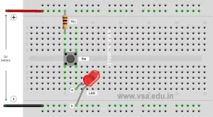
- PE-B1: LED on/off Circuit
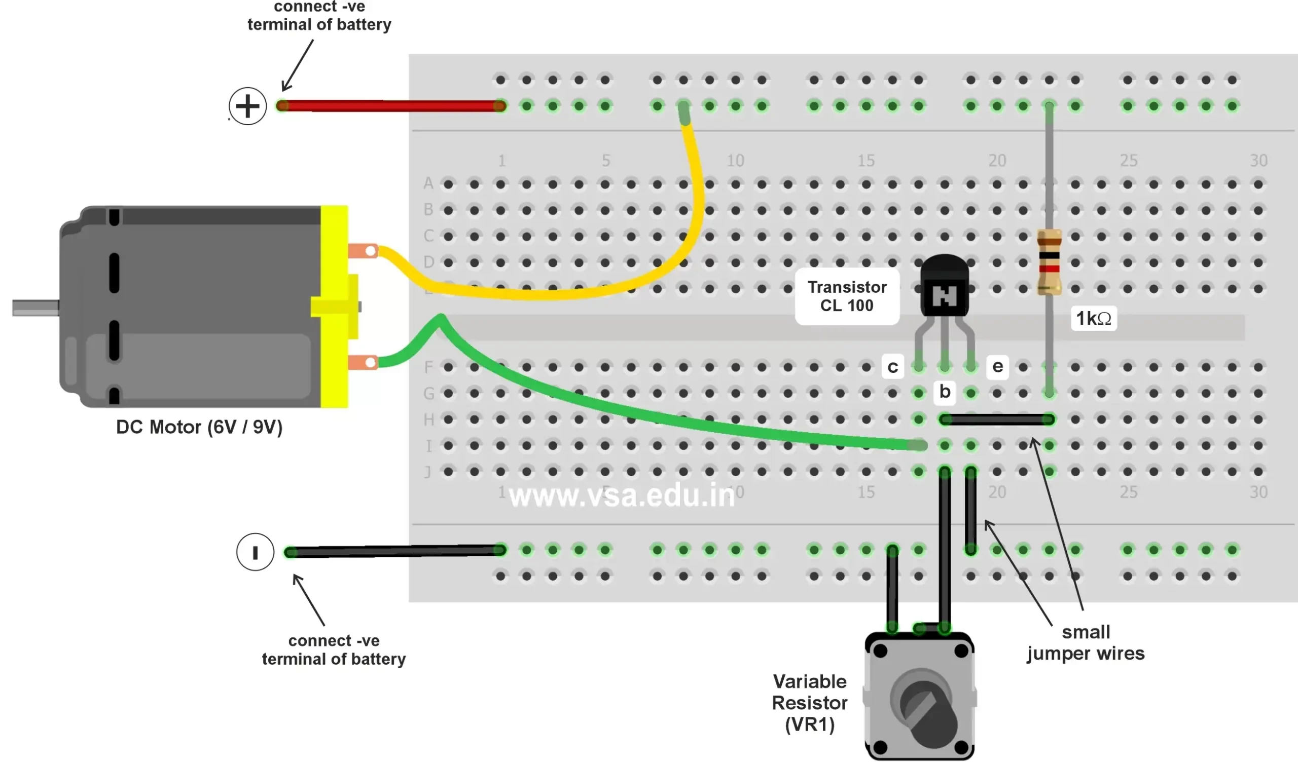
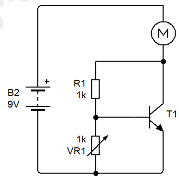
- PE-B11: DC Motor Speed Control Circuit
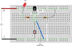
- PE-B13: Automatic Street Light Control Circuit
In this circuit when we rotate the variable resistor clockwise, the speed of motor increases and when we rotate it anti-clockwise the speed of motor decreases.
Download the set of Practical Electronics Notes & Workbook and start constructing interesting circuits at home.
Page Contents
show
Details of material required
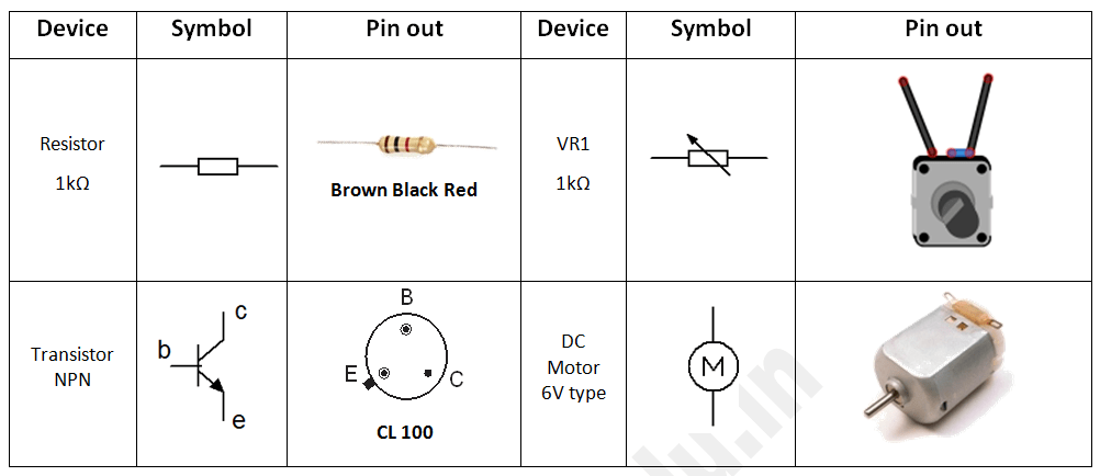
About Components
- Resistor: It protects the LED from burning.
- Buzzer: It produces alarm when it is ON.
- Transistor: It has 3 terminals – collector, base and emitter. The emitter is shown with arrow in the symbol.
Circuit diagram & Working
Circuit Diagram

Buy complete workbook of Practical Electronics just for Rs.49. The downloadable PDF copy contains 15 basic projects of practical electronics with complete details. It will help you construct more advanced circuits in practical electronics.