- How to use Arrays in Arduino coding?
- How to save Arduino Serial data in TXT, CSV and Excel file without using data logger shield?
- What to do if the theme editor option in WordPress dashboard disappeared?
- How analog pin works & how PWM signal is obtained in Arduino UNO/Nano?
The analogWrite() function writes a pseudo-analog value using hardware enabled pulse width modulation (PWM) process to an output pin marked PWM (~).
In new type of Arduino boards with the ATMeaga168 chip, the pins 3, 5, 6, 9, 10, and 11 work as PWM pins. Older Arduino board with an ATMega8 chip has only pins 9, 10, and 11 as PWM pins. The value can be specified as a variable or constant with a value from 0-255.
analogWrite(pin, value); // writes 'value' to analog 'pin'A value of 0 generates a steady 0V output at the specified pin and a value of 255 generates a steady 5V output at the specified pin. For values in between 0 and 255, the pin rapidly changes its voltage from 0 and 5V.
Let us see this process with a graphical example, as follows:
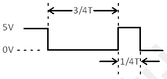
The value “64” is ¼ of 256. So if you take value=64, then the PWM signal will remain at 0V for ¾ of the time and at 5V ¼ of the time.
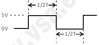
The value of “128” is ½ of 256. So if you take value=128, then the PWM signal will remain 0V for ½ of the time and at 5V for remaining ½ of the time.
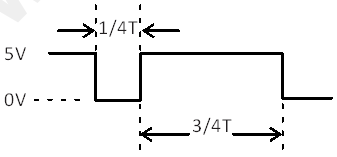
The value “192” is ¾ of 256. So if you take value=192, then the PWM signal will remain at 0V for ¼ of the time and at 5V ¾ of the time.
Now as this is a hardware function, the pin will generate a steady wave after a call to analogWrite in the background until next call to analogWrite (or a call to digitalRead or digitalWrite on same pin).
Note: Analog pins are never declared as INPUT or OUTPUT first in the program, unlike digital pins.
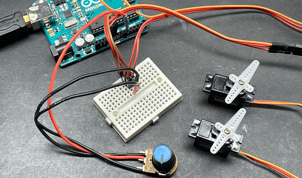
In following example, we will read the analog value from the analog pin and convert the value by dividing it by 4. Thus we will create PWM signal on the pin.
int led = 10; // LED with 330Ω resistor on pin 10
int potpin = 0; // center pin of pot connected to analog pin A0
int value; // value for reading

void setup()
{
  // no setup required
}

void loop()
{
  value = analogRead(potpin); // sets 'value' equal to 'potpin'
  value = value / 4; // converts 0-1023 to 0-255
  analogWrite(led, value); // outputs PWM signal to led
  delay(20); // delay added for testing
}