- AR-AD1: Sanguinoscope Blood Group Typing Project
- AR-AD2: Arduino Advanced Calculator
- AR-AD3: Arduino based Fastest Figure First Controlling System for Quiz Competition
- Convert Text into Morse Code with beeps & back into Text with Arduino
This code is updated with addition of one more switch for the judge. The details are given as human comments in the code. So the connections of the 5+1 switches are now different.
Please read carefully.
With this system we can detect the fastest finger first action in a quiz competition conducted in schools & colleges. For this project you require following components.
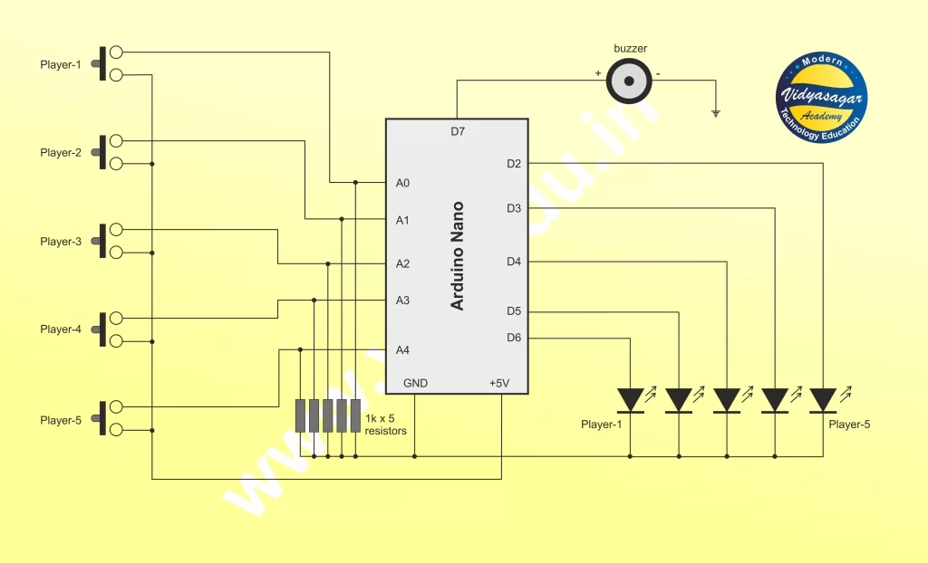
======= Connection details =======
Switches connections:
player1: A0, player2: A1, player3: A2, player4: A3, player5: A4
Judge: A5
LED1: pin-D2, LED2: pin-D3, LED3: pin-D4, LED4: pin-D5, LED5: pin-D6
Buzzer: pin-D7
Page Contents
show
Required Components
- Arduino UNO/Nano – 1
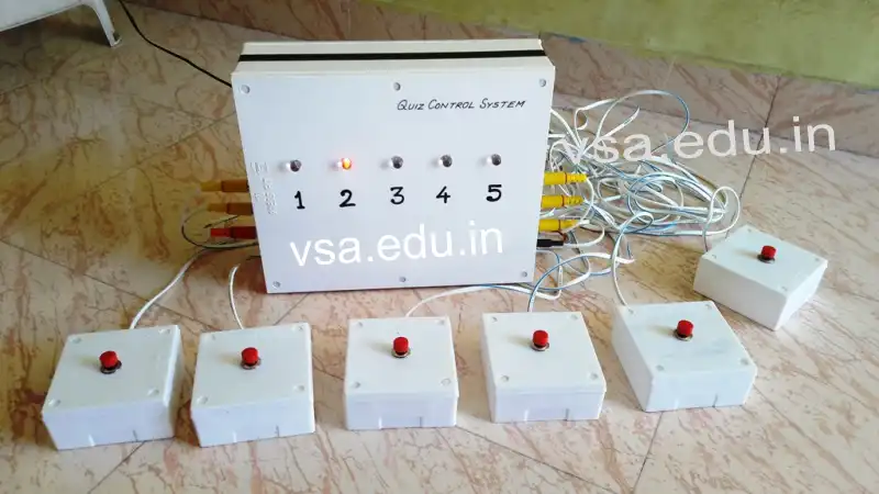
- 5mm Red LEDs – 5 (not shown in circuit. Connect 5mm and 10mm LEDs in parallel. Fit 5 LEDs on one side of the white box and 5 LEDs on other side. One side of the box will serve as display for contestants and judges and other side of the box will serve as display to the public, who are watching the competition)
- 10mm Red LEDs – 5
- RC sockets – 5 (not shown in circuit, but can be seen in photograph)
- RC pins – 5 (not shown in circuit, but can be seen in photograph)
- 1k resistors – 5
- 12V/9V adapter socket – 1 (you can use a socket to power the system through external power supply like using a 12V/9V DC Adapter)
- 9V, 1A transformer – 1
- 1N4007 diodes – 2
- Regulator IC 7805 – 1
- 1000uF capacitor – 2
- Small size zero PCB – 1 (solder the circuit components on it)
- PVC boxes 10” x 12” – 2 (the two pvc boxes are fitted back to back on each other so that the complete box can be easily placed on a table with firm base)
- PVC boxes 4” x 4” – 5 (in photograph of the project 6 small white boxes are shown, but as the code is designed to reset the system itself automatically, so 6th box is not necessary)
- Push-to-on switches – 5 (in photograph of the project 6 small white boxes are shown, but as the code is designed to reset the system itself automatically, so 6th switch is not necessary)
- Connecting wires, etc.
The Code
/* This code was developed by Vidyasagar Academy Akola,
 * www.vsa.edu.in
 * License: You can use it for any purpose as long as you don't
 * claim that you are its author and
 * you don't alter License terms and
 * formulations (lines 1-10 of this file).
 * Project: The 5 Channel Quiz Controlling System with auto reset using Arduino nano
 * Date of Creation: 17.02.2020
 * Date of Update: 08.08.2024
*/

/*
    ======= Connection details =======
    Switches connections:
    player1: A0, player2: A1, player3: A2, player4: A3, player5: A4
    Judge: A5
    LED1: pin-D2, LED2: pin-D3, LED3: pin-D4, LED4: pin-D5, LED5: pin-D6
    Buzzer: pin-D7
*/
int x=0;
int LED1=2;
int LED2=3;
int LED3=4;
int LED4=5;
int LED5=6;
int buzzer=7;

void setup()
{
  pinMode(A0,INPUT); // player1 switch input
  pinMode(A1,INPUT); // player2 switch input
  pinMode(A2,INPUT); // player3 switch input
  pinMode(A3,INPUT); // player4 switch input
  pinMode(A4,INPUT); // player5 switch input
  pinMode(A5,INPUT); // judge switch input

  pinMode(LED1,OUTPUT);
  pinMode(LED2,OUTPUT);
  pinMode(LED3,OUTPUT);
  pinMode(LED4,OUTPUT);
  pinMode(LED5,OUTPUT);

  pinMode(buzzer,OUTPUT);
  reset();
  delay(1000);
}

void loop()
{
  int a=digitalRead(A0);
    int b=digitalRead(A1);
      int c=digitalRead(A2);
        int d=digitalRead(A3);
          int e=digitalRead(A4);
            int judge=digitalRead(A5);

  /* Here at the start of 1st round, judge presses his button.
   * So the session starts.
   * When any contestant presses his/her button, the buttons of
   * other contestants will be disabled.
   * In this way, the 1st session is over.
   * Now since 1st session is over, the value of x = 2 in the code,
   * so any contestant cannot press his/her switch before the start
   * of the new session.
   * Now when judge presses his button, the value of x = 1
   * So new session can start.
   * In this way automatic RESET of this circuit is removed.
   */
  if(judge==LOW)
  {
    reset();
    x=1;

  }
  else
    x=2;

  if(a==LOW) // if player1 presses button
  {
    if(x==1) // check if x is 1, if yes then execute the code
    {
      digitalWrite(buzzer,HIGH); // buzzer alert that a switch is pressed
      digitalWrite(LED1,HIGH);
      x++;

      delay(3000);
      digitalWrite(buzzer,LOW);
    }
  }

  if(b==LOW) // if player2 presses button
  {
    if(x==1) // check if x is 1, if yes then execute the code
    {
      digitalWrite(buzzer,HIGH); // buzzer alert that a switch is pressed
      digitalWrite(LED2,HIGH);
      x++;

      delay(3000);
      digitalWrite(buzzer,LOW);
    }
  }

  if(c==LOW) // if player3 presses button
  {
    if(x==1) // check if x is 1, if yes then execute the code
    {
      digitalWrite(buzzer,HIGH); // buzzer alert that a switch is pressed
      digitalWrite(LED3,HIGH);
      x++;

      delay(3000);
      digitalWrite(buzzer,LOW);
    }
  }

  if(d==LOW) // if player4 presses button
  {
    if(x==1) // check if x is 1, if yes then execute the code
    {
      digitalWrite(buzzer,HIGH); // buzzer alert that a switch is pressed
      digitalWrite(LED4,HIGH);
      x++;

      delay(3000);
      digitalWrite(buzzer,LOW);
    }
  }

  if(e==LOW) // if player5 presses button
  {
    if(x==1) // check if x is 1, if yes then execute the code
    {
      digitalWrite(buzzer,HIGH); // buzzer alert that a switch is pressed
      digitalWrite(LED5,HIGH);
      x++;

      delay(3000);
      digitalWrite(buzzer,LOW);
    }
  }

   if(x==2)
   {
      delay(3000);
      digitalWrite(LED1,LOW);
      digitalWrite(LED2,LOW);
      digitalWrite(LED3,LOW);
      digitalWrite(LED4,LOW);
      digitalWrite(LED5,LOW);
   }
}

  void reset()
  {
    for(int i=0;i<4;i++)
    {
    digitalWrite(LED1,HIGH);
    digitalWrite(LED2,HIGH);
    digitalWrite(LED3,HIGH);
    digitalWrite(LED4,HIGH);
    digitalWrite(LED5,HIGH);
    digitalWrite(buzzer,HIGH);
    delay(100);
    digitalWrite(LED1,LOW);
    digitalWrite(LED2,LOW);
    digitalWrite(LED3,LOW);
    digitalWrite(LED4,LOW);
    digitalWrite(LED5,LOW);
    digitalWrite(buzzer,LOW);
    delay(100);
    }
  }
Circuit Diagram

The Prototype of Project


please provide image from almost every angle of your project from real life please
Sorry. The prototype is sold. We don’t have its photos now.
But I can explain its construction details.
Use two PVC white boards (size: 10″x12″) stuck together back to back, as shown.
The use 5 small square boxes to fit 5 push-to-on buttons with wires and pins for each channel connectivity.
Then install your Arduino nano circuit, or Uno circuit inside one of the stuck white board and connect 9V DC adapter socket on one side of the board.
Connect the adapter externally to start the working.
If you want the project to be readily prepared for you, we can provide such paid service.
Well we found out some photographs of the project given on this link: https://vsa.edu.in/ad3-arduino-based-fastest-figure-first-controlling-system-for-quiz-competition/#The_Prototype_of_Project
Hey, Thank you very much for the help, Now i have made the project properly working
That’s great!
We are pleased to help you…!
Please send photographs of the project, so that we will upload them on the same link with your name, so that more people will be inspired from your project to build it.
Please send the photos on our email address: dsvakola@gmail.com
Hey i found out 1 more problem that as it checks one by one if the button is pressed or not if 2 contestants have pressed their even before the round starts, it will show that button 1 is pressed first
Any solution regarding this ….. BTW thanks for the referral code
I wanted to say that if button1 and button 3 are pressed at same time before round starts and as round starts our system will show that button 1 was pressed first as it checks button1 the first
Oh…!
I never thought about this problem of starting the round.
Ok.
Please give me some time, I will try to figure out and write new code for it.
The code is now updated as per your valuable suggestion.
Now the connections of the 5+1 switches are changed.
======= Connection details =======
Switches connections:
player1: A0, player2: A1, player3: A2, player4: A3, player5: A4
Judge: A5
LED1: pin-D2, LED2: pin-D3, LED3: pin-D4, LED4: pin-D5, LED5: pin-D6
Buzzer: pin-D7
/* Here at the start of 1st round, judge presses his button.
* So the session starts.
* When any contestant presses his/her button, the buttons of
* other contestants will be disabled.
* In this way, the 1st session is over.
* Now since 1st session is over, the value of x = 2 in the code,
* so any contestant cannot press his/her switch before the start
* of the new session.
* Now when judge presses his button, the value of x = 1
* So new session can start.
* In this way automatic RESET of this circuit is removed.
*/
Please check and reply to this comment.
Thanks for the feedback.
I had replied to your problem with solution. Please check above comments and share your experience.
Did it solve your problem?