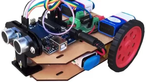
This a lab tested code of White line following robot using 8051 MUC. When there is black below an IR sensor, its output is binary-1. When there is white below an IR sensor, its output is binary-0. This code is suitable for OVAL SHAPED SIMPLE WHITE TRACKS. For complicated white tracks i.e. having many steep turns, USE POWER TURN INSTEAD OF SOFT TURN i.e. rotate one motor forward and other backward simultaneously.
1. Introduction
A Line Following Robot is an autonomous robot that follows a pre-defined path, typically a white or black line on a contrasting background. In this project, we use an 8051 Microcontroller to implement a white line follower. The robot senses the line using IR sensors and moves accordingly.
2. Components Required
- 8051 Microcontroller (AT89C51)
- IR Sensors (2 pairs)
- Motors (DC Motors)
- Motor Driver IC (L293D)
- Chassis
- Wheels
- Power Supply (Battery 9-12V)
- Crystal Oscillator (11.0592 MHz)
- Capacitors and Resistors
- Connecting Wires
Software required
- Keil µVision (for C programming) – download from this link
- MIDE51 or any assembler (for ALP) – download from this link
- Flash/Programmer Tool (e.g., ProgISP, TopWin) to burn the program into 8051 – download from this link
3. Working Principle
The robot works based on IR sensors that detect the white line. IR sensors emit infrared light, which is either absorbed or reflected depending on the surface:
- White Surface: Reflects most IR light back to the sensor.
- Black Surface: Absorbs most IR light, little to no reflection.
The sensor output is processed by the 8051 microcontroller, which sends control signals to the motor driver IC (L293D). The motors are turned ON/OFF based on the sensor inputs, enabling the robot to follow the white line.
4. Circuit Diagram
The connections are as follows:
- IR Sensors: Output pins are connected to the P1.0 and P1.1 pins of the 8051 microcontroller.
- Motor Driver IC (L293D): Input pins are connected to P2.0 to P2.3 pins of the 8051 microcontroller.
- Motors: Connected to the output pins of the L293D.
- Power Supply: Provides power to the motors and 8051 circuit.
5. Logic for Line Following
- If both sensors detect white (line), move FORWARD.
- If the left sensor detects black, turn RIGHT.
- If the right sensor detects black, turn LEFT.
- If both sensors detect black (no line), STOP.
6. Program Code and Explanation
Below is the complete code for the white line following robot with line-by-line explanations.
Code Initialization
#include <reg51.h>      // Header file for 8051 Microcontroller
sbit left_sensor = P1^0;   // Left IR sensor connected to Pin P1.0
sbit right_sensor = P1^1;  // Right IR sensor connected to Pin P1.1
sbit motor1_a = P2^0;  // Motor1 (LEFT Motor) Control Pin A
sbit motor1_b = P2^1;  // Motor1 Control Pin B
sbit motor2_a = P2^2;  // Motor2 (RIGHT Motor) Control Pin A
sbit motor2_b = P2^3;  // Motor2 Control Pin B
Explanation
#include <reg51.h>:Includes the header file for the 8051 microcontroller.sbitis used to define sensor and motor control pins:left_sensor and right_sensorare connected to P1.0 and P1.1 respectively.motor1_a, motor1_b, motor2_a, motor2_bare control pins for the motor driver IC (L293D).
Motor Control Functions
void move_forward() {
    motor1_a = 1; motor1_b = 0;  // Left motor moves forward
    motor2_a = 1; motor2_b = 0;  // Right motor moves forward
}

void move_left() {
    motor1_a = 0; motor1_b = 0;  // Left motor stops
    motor2_a = 1; motor2_b = 0;  // Right motor moves forward
}

void move_right() {
    motor1_a = 1; motor1_b = 0;  // Left motor moves forward
    motor2_a = 0; motor2_b = 0;  // Right motor stops
}

void stop() {
    motor1_a = 0; motor1_b = 0;  // Left motor stops
    motor2_a = 0; motor2_b = 0;  // Right motor stops
}
Explanation
move_forward():Both motors move forward to drive the robot straight.move_left():The right motor moves forward while the left motor stops, making the robot turn left.move_right():The left motor moves forward while the right motor stops, making the robot turn right.stop():Both motors stop, halting the robot.
7. Conditional Movement Logic
void main() {
    while (1) {   // Infinite loop
        if (left_sensor == 1 && right_sensor == 1) {
            move_forward();  // Move forward when both sensors detect white
        }

        else if (left_sensor == 0 && right_sensor == 1) {
            move_right();  // Turn right when left sensor detects black
        }

        else if (left_sensor == 1 && right_sensor == 0) {
            move_left();  // Turn left when right sensor detects black
        }

        else if (left_sensor == 0 && right_sensor == 0) {
            stop();  // Stop when both sensors detect black
        }
    }
}
Explanation
while (1):Creates an infinite loop so the robot runs continuously.left_sensor == 1 && right_sensor == 1:Both sensors detect white, so move forward.left_sensor == 0 && right_sensor == 1:Left sensor detects black, so turn right.left_sensor == 1 && right_sensor == 0:Right sensor detects black, so turn left.left_sensor == 0 && right_sensor == 0:Both sensors detect black, so stop.- The motor control functions
(move_forward, move_right, move_left, stop)are called based on sensor inputs.
8. Explanation of Working
- The IR sensors sense the line and send digital signals (0 or 1) to the 8051 microcontroller.
- The microcontroller checks the sensor input and calls the appropriate motor control function.
- The L293D motor driver IC receives signals from the microcontroller and controls the motors accordingly.
- The robot moves forward, turns left, or turns right based on the sensor data.
The White Line Following Robot using the 8051 Microcontroller successfully detects and follows a white line. It uses IR sensors for detection and a motor driver IC to control the motors. This project demonstrates the concept of autonomous robots and forms the basis for more advanced robotic systems.
9. Assembly Language Code
If you are interested to make this project using Assembly Language Program (ALP) then we have also given it for your project. Read the following points step by step and use them to make your project a great success! All the best…!
Initialization and Pin Definitions
ORG 0000H           ; Starting address of the program
; Pin Definitions
LEFT_SENSOR  EQU P1.0  ; Left IR Sensor at Pin P1.0
RIGHT_SENSOR EQU P1.1  ; Right IR Sensor at Pin P1.1
MOTOR1_A     EQU P2.0  ; Left Motor Pin A
MOTOR1_B     EQU P2.1  ; Left Motor Pin B
MOTOR2_A     EQU P2.2  ; Right Motor Pin A
MOTOR2_B     EQU P2.3  ; Right Motor Pin B
Explanation
ORG 0000H:Tells the assembler to start placing the program at memory address0000H.EQUis used to define the pins for sensors and motors for clarity and easier coding.LEFT_SENSOR and RIGHT_SENSORrefer to the two IR sensors connected toP1.0andP1.1.MOTOR1_A, MOTOR1_B, MOTOR2_A, and MOTOR2_Bcontrol the two motors.
Motor Control Subroutines
MOVE_FORWARD:
SETB MOTOR1_A   ; Left Motor moves forward
    CLR  MOTOR1_B
    SETB MOTOR2_A   ; Right Motor moves forward
    CLR  MOTOR2_B
    RET
MOVE_LEFT:
CLR  MOTOR1_A   ; Left Motor stops
    CLR  MOTOR1_B
    SETB MOTOR2_A   ; Right Motor moves forward
    CLR  MOTOR2_B
    RET
MOVE_RIGHT:
SETB MOTOR1_A   ; Left Motor moves forward
    CLR  MOTOR1_B
    CLR  MOTOR2_A   ; Right Motor stops
    CLR  MOTOR2_B
    RET
STOP_MOTORS:
CLR  MOTOR1_A   ; Left Motor stops
    CLR  MOTOR1_B
    CLR  MOTOR2_A   ; Right Motor stops
    CLR  MOTOR2_B
    RET
Explanation
- MOVE_FORWARD:
SETB MOTOR1_AandSETB MOTOR2_Aturn ON both motors to move forward. CLR MOTOR1_BandCLR MOTOR2_Bensure motors rotate in the forward direction.- MOVE_LEFT: Stops the left motor (
CLR MOTOR1_A and CLR MOTOR1_B). - Moves the right motor forward (
SETB MOTOR2_A). - MOVE_RIGHT: Moves the left motor forward (
SETB MOTOR1_A). - Stops the right motor (
CLR MOTOR2_A and CLR MOTOR2_B). - STOP_MOTORS: Stops both motors by clearing all motor pins.
- RET: Returns from the subroutine to the main program.
Main Program Logic
MAIN:
MOV P1, #0FFH      ; Set P1 as input for sensors
MOV P2, #00H       ; Set P2 as output for motors
CHECK_SENSORS:
JB LEFT_SENSOR, CHECK_RIGHT   ; If LEFT_SENSOR = 1 (white), check right sensor
JNB RIGHT_SENSOR, TURN_RIGHT  ; If RIGHT_SENSOR = 0 (black), turn right
SJMP MOVE_LEFT                ; Otherwise, turn left
CHECK_RIGHT:
JB RIGHT_SENSOR, MOVE_FWD     ; If RIGHT_SENSOR = 1 (white), move forward
SJMP TURN_LEFT                ; Otherwise, turn left
MOVE_FWD:
ACALL MOVE_FORWARD  ; Call subroutine to move forward
SJMP CHECK_SENSORS  ; Go back and check sensors
TURN_LEFT:
ACALL MOVE_LEFT     ; Call subroutine to turn left
SJMP CHECK_SENSORS  ; Go back and check sensors
TURN_RIGHT:
ACALL MOVE_RIGHT    ; Call subroutine to turn right
SJMP CHECK_SENSORS  ; Go back and check sensors
Explanation
- MAIN:
MOV P1, #0FFH: Configures Port 1 (P1) as input for the sensors. - MOV P2, #00H: Configures Port 2 (P2) as output for controlling motors.
- CHECK_SENSORS: JB LEFT_SENSOR, CHECK_RIGHT: Checks if the left sensor detects white (1). If true, jump to CHECK_RIGHT.
- JNB RIGHT_SENSOR, TURN_RIGHT: If the right sensor detects black (0), jump to TURN_RIGHT.
- SJMP MOVE_LEFT: Otherwise, turn left.
- CHECK_RIGHT: JB RIGHT_SENSOR, MOVE_FWD: If the right sensor detects white (1), move forward.
- SJMP TURN_LEFT: Otherwise, turn left.
- Motor Movements: ACALL MOVE_FORWARD, MOVE_LEFT, or MOVE_RIGHT calls the respective motor control subroutine.
- Looping: SJMP CHECK_SENSORS: Continuously loops back to check sensor inputs.
- END: End of the program
10. Working Flow
- Initialization: Set the sensor pins as input and motor pins as output.
- Sensor Checking: Continuously monitor the left and right sensors.
- Decision Making: If both sensors detect white → Move Forward.
- If left sensor detects black → Turn Right.
- If right sensor detects black → Turn Left.
- If both sensors detect black → Stop.
- Motor Control: Appropriate motor control subroutines are called based on the sensor conditions.
The Assembly Language Program (ALP) effectively controls the white line-following robot using sensor inputs and motor control logic. It utilizes subroutines to manage motor movements and loops continuously to ensure real-time line following.
Make sure you download the software tools from their official links and follow their installation instructions carefully. Comment at the bottom of this post if need guidance during installation or usage!


