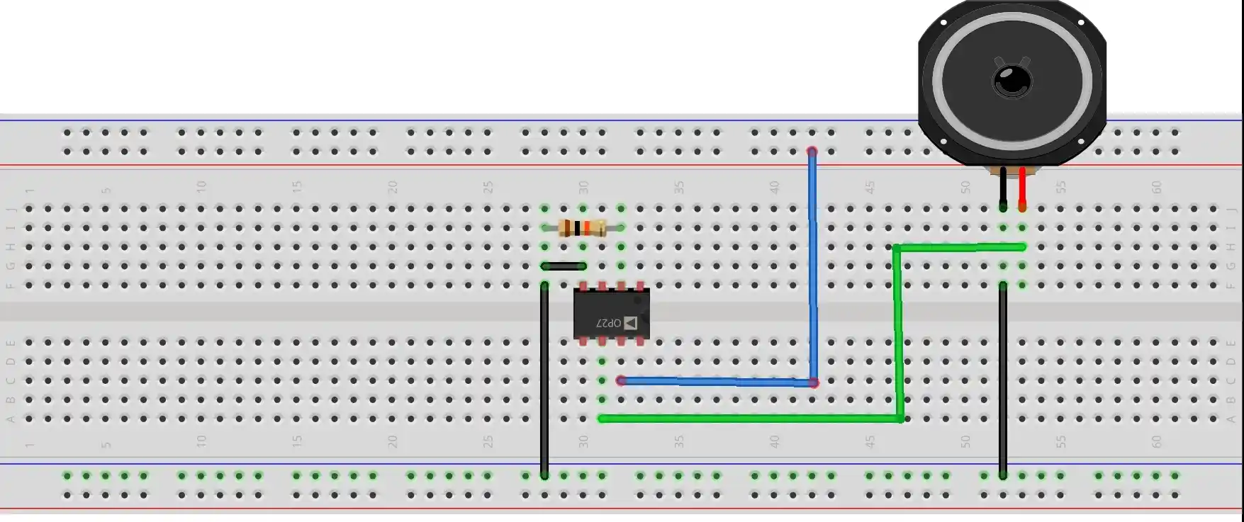
The Differential Amplifier is the super quality amplifier used in operational amplifiers. As its name implies, it amplifies the difference of two input signals i.e. V1 and V2 and gives the output. Hence it is called as differential amplifier.
BASIC CONCEPT
The ideal differential amplifier circuit uses two identical transistors T1 and T2 and two identical resistors Rc1 and Rc2. So the circuit is perfectly balanced.

The Four Types
We can use the differential amplifier in four different types, they are:
Dual input and balanced output
This combination uses both inputs with both outputs. Two different input signals V1 and V2 are connected across input-1 and input-2 and their amplified difference is taken across collectors of T1 and T2.
Dual input and unbalanced output
This combination uses both inputs with only one output. Two different input signals V1 and V2 are connected across input-1 and input-2 and the amplified output is taken across the collector of transistor T1 only.
Single input and balanced output
This combination uses only one input with both outputs i.e. (either input-1 or input-2). One input signal V1 OR V2 is connected across input-1 or input-2 and the amplified output is taken across collectors of T1 and T2.
Single input and unbalanced output
This combination uses only one input with one output i.e. (either input-1 or input-2). One input signal V1 OR V2 is connected across input-1 or input-2 and the amplified output is taken across collector of T1 only.
The circuit has two inputs terminals: input-1 called inverting input terminal. The output signal is 180° out of phase with inverting input. And input-2 non-inverting input terminal. The output signal is in phase with non-inverting input.
For example, if we apply negative voltage at inverting terminal we get positive voltage at output. Similarly, if we apply positive voltage at non-inverting terminal, we get positive voltage at output.
Explanation of Differential Amplifier
Modes of differential amplifier
Differential mode input: In this mode, we use dual input, unbalanced output type of differential amplifier circuit. The output voltage of the circuit is given by –
Vo ∝ (V1 – V2) … suppose V1 – V2 = Vid ∴ Vo ∝ Vid
∴ Vo = A.(V1 – V2) … where, A is called the gain of the differential amplifier
Now there are two possible conditions of input signals, in this mode:
Condition #1: If V1 = V2 in magnitude, but opposite in polarities, then the output will be –
Vo = A.(V1 – (-V1)) = 2AV1 or Vo = A.(V2 – (-V2)) = 2AV2
In this case, the gain of the circuit is doubled.
Condition #2: If V1 ≠ V2 then we get the output as follows –
Vo = A.(V1 – V2) ≠ 0 i.e. |A| > 0
Thus in both conditions, the absolute value of gain is always greater than zero.
This gain is called differential mode gain (ADM).
Common mode input: In this mode also, we use dual input, unbalanced output type of differential amplifier circuit. Now suppose V1 = V2 both in magnitudes and polarity, then –
Vi = A.(V1 – V2) = (V1 – V1) = 0
In this condition, we say that the gain of the circuit is zero i.e. A = 0. This type of gain is called common mode gain (ACM).
The ratio of differential mode gain to common mode gain is called as CMRR – Common Mode Rejection Ratio.
CMRR = ADM / ACM = ∞
Because common mode gain ACM = 0
CMRR decides the quality of differential amplifier and shows its ability to reject external-noise i.e. common signals at input-1 and input-2.
The practical differential amplifier circuit is not balanced, so it has small gain in common mode also i.e.| ACM | > 0. Due to this small noise enters into the circuit and gets amplified.


