1. Introduction
What is Table Top Edge Avoiding Robot?
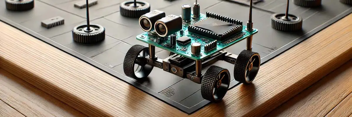
Table Top Edge Avoiding Robot using 8051 Microcontroller is an autonomous robot designed to avoid falling off a table edge. It uses IR sensors to detect the absence of a surface (edge detection) and changes its direction accordingly to avoid falling. The 8051 Microcontroller processes sensor data and controls the motors to achieve edge avoidance.
2. Components Required
- 8051 Microcontroller (AT89C51)
- IR Sensors (2 pairs)
- DC Motors
- Motor Driver IC (L293D)
- Chassis
- Wheels
- Power Supply (Battery 9-12V)
- Crystal Oscillator (11.0592 MHz)
- Capacitors and Resistors
- Connecting Wires
Software required
- Keil µVision (for C programming) – download from this link
- MIDE51 or any assembler (for ALP) – download from this link
- Flash/Programmer Tool (e.g., ProgISP, TopWin) to burn the program into 8051 – download from this link
3. Working Principle
The IR sensors are placed at the front corners of the robot. The table’s surface reflects the IR light, while the absence of the surface (edge) fails to reflect it, making the IR sensor output LOW (0). The robot uses these sensor outputs to make decisions:
- Both sensors on table → Move Forward.
- Left sensor detects edge → Turn Right.
- Right sensor detects edge → Turn Left.
- Both sensors detect edge → Stop.
4. Circuit Diagram
The connections are as follows:
- IR Sensors: Outputs connected to pins P1.0 and P1.1.
- Motor Driver IC (L293D): Inputs connected to pins P2.0 to P2.3.
- Motors: Connected to L293D outputs.
- Power Supply: Supplies power to the motors and the 8051 microcontroller.
5. Logic for Edge Avoidance
- If both sensors detect the table → Move Forward.
- If left sensor detects the edge → Turn Right.
- If right sensor detects the edge → Turn Left.
- If both sensors detect the edge → Stop.
6. Program Code with Explanation
Here is the complete program written in Embedded C for the Table Top Edge Avoiding Robot.
6.1 Initialization and Pin Definitions
#include<reg51.h>
sbit left_sensor=P1^0;
sbit right_sensor=P1^1;
sbit motor1_a=P2^0;
sbit motor1_b=P2^1;
sbit motor2_a=P2^2;
sbit motor2_b=P2^3;
Explanation
- #include<reg51.h>: Includes the 8051 microcontroller header file.
- sbit: Defines pins for sensors and motor control:
- left_sensor and right_sensor: Inputs for IR sensors.
- motor1_a and motor1_b: Control the left motor.
- motor2_a and motor2_b: Control the right motor.
6.2 Motor Control Functions
void move_forward() {
     motor1_a=1;motor1_b=0;
     motor2_a=1;motor2_b=0;
}

void move_left() {
     motor1_a=0;motor1_b=0;
     motor2_a=1;motor2_b=0;
}

     void move_right() {
     motor1_a=1;motor1_b=0;
     motor2_a=0;motor2_b=0;
}

void stop() {
     motor1_a=0;motor1_b=0;
     motor2_a=0;motor2_b=0;
}
Explanation
- move_forward(): Both motors move forward.
- motor1_a=1;motor1_b=0 → Left motor forward.
- motor2_a=1;motor2_b=0 → Right motor forward.
- move_left(): Left motor stops, and the right motor moves forward to turn left.
- move_right(): Right motor stops, and the left motor moves forward to turn right.
- stop(): Both motors stop, halting the robot.
6.3 Main Program Logic
void main() {

while(1) {
        if(left_sensor==1&&right_sensor==1) {
        move_forward();
    }

        else if(left_sensor==0&&right_sensor==1) {
        move_right();
    }

        else if(left_sensor==1&&right_sensor==0) {
        move_left();
    }

        else if(left_sensor==0&&right_sensor==0) {
        stop();
   }
 }
}
Explanation
- while(1): Infinite loop for continuous edge detection and movement.
- Condition Checks: if(left_sensor==1&&right_sensor==1): Both sensors detect the table surface → Move Forward.
- else if(left_sensor==0&&right_sensor==1): Left sensor detects an edge → Turn Right.
- else if(left_sensor==1&&right_sensor==0): Right sensor detects an edge → Turn Left.
- else if(left_sensor==0&&right_sensor==0): Both sensors detect edges → Stop the robot.
7. Flowchart
Here is the flow of the robot operation:
- Start → Initialize ports and pins.
- Read Sensor Values.
- Check Conditions: Both sensors detect table → Move Forward.
- Left sensor detects edge → Turn Right.
- Right sensor detects edge → Turn Left.
- Both sensors detect edge → Stop.
- Repeat Steps Continuously.
8. Assembly Language Program (ALP)
This code is given to the students and hobbyists who are interested to work with ALP code of the project. Try it…! Its perfectly working, as it is tested in Vidyasagar Academy Lab.
ORG 0000H           ; Starting address of the program

; Pin Definitions
LEFT_SENSOR  EQU P1.0
RIGHT_SENSOR EQU P1.1
MOTOR1_A     EQU P2.0
MOTOR1_B     EQU P2.1
MOTOR2_A     EQU P2.2
MOTOR2_B     EQU P2.3

; Motor Control Subroutines
MOVE_FORWARD:
    SETB MOTOR1_A
    CLR  MOTOR1_B
    SETB MOTOR2_A
    CLR  MOTOR2_B
    RET

MOVE_LEFT:
    CLR  MOTOR1_A
    CLR  MOTOR1_B
    SETB MOTOR2_A
    CLR  MOTOR2_B
    RET

MOVE_RIGHT:
    SETB MOTOR1_A
    CLR  MOTOR1_B
    CLR  MOTOR2_A
    CLR  MOTOR2_B
    RET

STOP_MOTORS:
    CLR  MOTOR1_A
    CLR  MOTOR1_B
    CLR  MOTOR2_A
    CLR  MOTOR2_B
    RET

; Main Program Logic
MAIN:
    MOV P1, #0FFH       ; Set P1 as input for sensors
    MOV P2, #00H        ; Set P2 as output for motors

CHECK_SENSORS:
    JB LEFT_SENSOR, CHECK_RIGHT
    JNB RIGHT_SENSOR, TURN_RIGHT
    SJMP TURN_LEFT

CHECK_RIGHT:
    JB RIGHT_SENSOR, MOVE_FWD
    SJMP TURN_LEFT

MOVE_FWD:
    ACALL MOVE_FORWARD
    SJMP CHECK_SENSORS

TURN_LEFT:
    ACALL MOVE_LEFT
    SJMP CHECK_SENSORS

TURN_RIGHT:
    ACALL MOVE_RIGHT
    SJMP CHECK_SENSORS

STOP_ROBOT:
    ACALL STOP_MOTORS
    SJMP CHECK_SENSORS
END
9. Working
- IR Sensors: The sensors monitor the table surface continuously.
- Sensor Logic: When the table surface disappears (edge), the corresponding sensor sends a LOW signal to the microcontroller.
- Microcontroller: Processes the sensor inputs and decides the robot movement by controlling the motors.
- Motors: Receive signals from the L293D motor driver and perform actions like moving forward, turning left/right, or stopping.
10. Advantages
- Prevents the robot from falling off surfaces.
- Simple and cost-effective.
- Practical implementation of edge detection using IR sensors.
11. Conclusion
The Table Top Edge Avoiding Robot using the 8051 Microcontroller successfully detects table edges and avoids falling by changing its direction. The use of IR sensors ensures accurate edge detection and the 8051 processes the inputs to control motor movements. This project can be extended further for obstacle avoidance or more complex surface detection.
Make sure you download the software tools from their official links and follow their installation instructions carefully. Comment at the bottom of this post if need guidance during installation or usage!


