1. Introduction
The 8051 microcontroller is one of the most commonly used microcontrollers in embedded systems. It can be easily used to in DTMF Controlling System using 8051 Microcontroller. It provides easy interfacing for LEDs, sensors, and other peripherals. DTMF (Dual Tone Multi-Frequency) is a signal generated when keys are pressed on a mobile phone. This signal can be decoded using a DTMF decoder (e.g., MT8870 IC). The output of the decoder can be interfaced with the 8051 microcontroller to perform specific tasks.
2. How this project works?
- Two LEDs are connected to P1^0 and P1^7 pins of the 8051 microcontroller.
- A DTMF sensor is used to control the LEDs using a mobile phone.
- Pressing 1 on the phone toggles the first LED (P1^0).
- Pressing 2 toggles the second LED (P1^7).
This document includes:
- C Language Code explanation.
- Assembly Language Code explanation.
- Steps to burn the codes into the 8051 microcontroller.
3. Hardware and Software Requirements
Material required:
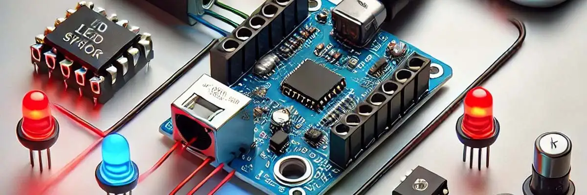
- 8051 Microcontroller (e.g., AT89C51)
- DTMF Decoder IC (e.g., MT8870)
- Two LEDs
- Resistors (330Ω for LEDs)
- Mobile Phone (as a keypad)
- Power Supply (5V)
- Connecting wires
- Breadboard
Software required:
- Keil µVision (for C programming) – download from this link
- MIDE51 or any assembler (for ALP) – download from this link
- Flash/Programmer Tool (e.g., ProgISP, TopWin) to burn the program into 8051 – download from this link
4. C Language Code
#include <reg51.h>
sbit LED1 = P1^0;  // First LED connected to P1^0
sbit LED2 = P1^7;  // Second LED connected to P1^7

void delay(unsigned int time) {
    unsigned int i, j;
    for (i = 0; i < time; i++)
        for (j = 0; j < 1275; j++);  // Delay generation
}

void main() {
    unsigned char input;
    LED1 = 0;  // Initialize both LEDs as OFF
    LED2 = 0;

    while (1) {
        input = P2;  // Read input from DTMF decoder (connected to Port 2)
        if (input == 0x01) {  // If '1' is pressed
            LED1 = ~LED1;     // Toggle LED1
            delay(100);       // Small delay to avoid debounce
        }

        if (input == 0x02) {  // If '2' is pressed
            LED2 = ~LED2;     // Toggle LED2
            delay(100);       // Small delay to avoid debounce
        }
    }
}
5. Assembly Language Program (ALP)
Here is the equivalent assembly language program:
ORG 0000H       ; Start of the program
START:
    MOV P1, #00H  ; Clear Port 1 (All LEDs OFF)
    MOV A, P2     ; Read DTMF input from Port 2
    CJNE A, #01H, CHECK2 ; Check if '1' is pressed
    CPL P1.0       ; Toggle LED1
    SJMP START

CHECK2:
    CJNE A, #02H, START ; Check if '2' is pressed
    CPL P1.7       ; Toggle LED2
    SJMP START
END
6. Procedure to Burn Code into 8051 Microcontroller
- Write the code in Keil µVision and compile it.
- Generate the HEX file by selecting Project → Build Target.
- Use a programmer like ProgISP or TopWin.
- Connect the 8051 microcontroller to the programmer.
- Load the HEX file into the programmer software and burn it to the microcontroller.
- For Assembly Language:
- Write the code in an assembler tool like MIDE51.
- Assemble the code to generate a HEX file.
- Follow the same steps to burn the HEX file into the microcontroller.
7. Conclusion
In this project, we demonstrated how to control two LEDs using the 8051 microcontroller and a DTMF sensor. The LEDs are toggled based on the DTMF signals (1 and 2) sent from a mobile phone. Both C code and Assembly Language were provided, and the procedure to burn the code into the microcontroller was explained.
This setup can be extended for home automation systems or other embedded applications requiring remote control using mobile phones and DTMF sensors.
Make sure you download the software tools from their official links and follow their installation instructions carefully. Comment at the bottom of this post if need guidance during installation or usage!