1. Introduction
A Black Line Following Robot is a simple autonomous robot that can detect and follow a black line on a white or light-colored surface. This robot is built using the 8051 Microcontroller (MUC), IR sensors, and DC motors. It is a widely popular project in robotics because of its simplicity and scope for learning embedded systems, motor control, and sensor interfacing.
In this project, IR sensors are used to detect the black line, and based on the sensor input, the 8051 MUC drives the motors to keep the robot on the line. With minor modifications, the robot can be scaled up for real-world applications.
2. Basic Principle of IR Sensor to Detect Black Line
The IR sensor is the key component that enables the robot to detect the black line. The sensor consists of two parts:
- IR Transmitter (LED): Emits infrared light.
- IR Receiver (Photodiode): Detects reflected IR light.
Principle
- A white surface reflects most of the IR light back to the receiver.
- A black surface absorbs the IR light, and very little or no light is reflected.
When the sensor is placed above the line, the amount of light received by the photodiode changes, generating different voltage levels. This signal is then processed by the microcontroller to determine the robot’s movement.
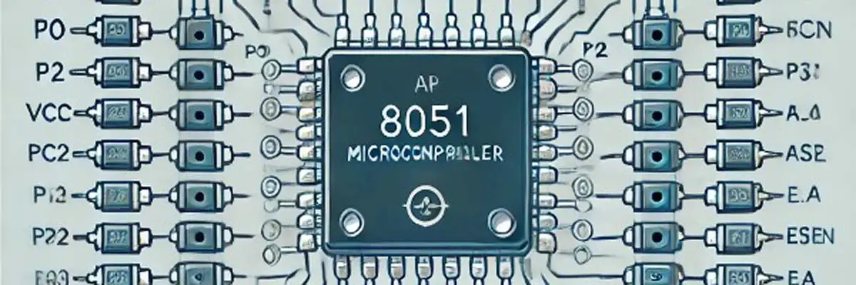
3. Details of 8051 Pin Configuration with Pin Diagram
The 8051 microcontroller has 40 pins, and for this project, specific pins are used to interface with sensors and motors:
- Port 1 (P1.0 to P1.7): Used to interface with the IR sensors. Each pin of Port 1 receives the sensor output.
- Port 2 (P2.0 to P2.3): Controls the motor driver. P2.0 and P2.1 control the left motor, while P2.2 and P2.3 control the right motor.
- VCC (Pin 40): Connect to a 5V power supply.
- GND (Pin 20): Connect to ground.
- XTAL1 and XTAL2 (Pins 19 and 18): Connect a 12 MHz crystal oscillator for clock input.
- RESET (Pin 9): Used to reset the microcontroller by applying a high signal momentarily.
The motors and IR sensors interact with the pins above to achieve the desired movements based on line detection.
Pin Connections in the Project
- P1.0 and P1.1: Input from Left and Right IR Sensors.
- P2.0 and P2.1: Output to Left and Right DC motors (Motor Driver).
- GND: Connected to the ground.
- VCC: Connected to +5V power supply.
4. Code in C Explanation with Code Snippets
The code is written in Embedded C to interface the IR sensors and control the motors.
Snippet 1: Define Pin Connections
#define LEFT_SENSOR P1_0
#define RIGHT_SENSOR P1_1
#define LEFT_MOTOR P2_0
#define RIGHT_MOTOR P2_1
Explanation: The IR sensors and motors are assigned to specific pins of Port 1 and Port 2 for easy reference.
Snippet 2: Main Control Logic
void main() {
    while (1) {
        if (LEFT_SENSOR == 0 && RIGHT_SENSOR == 0) { // Both sensors on black
            LEFT_MOTOR = 1;
            RIGHT_MOTOR = 1; // Move forward
        }

        else if (LEFT_SENSOR == 0) { // Left sensor on black
            LEFT_MOTOR = 0;
            RIGHT_MOTOR = 1; // Turn right
        }

        else if (RIGHT_SENSOR == 0) { // Right sensor on black
            LEFT_MOTOR = 1;
            RIGHT_MOTOR = 0; // Turn left
        }

        else { // Both sensors on white
            LEFT_MOTOR = 0;
            RIGHT_MOTOR = 0; // Stop
        }
    }
}
Explanation: The if conditions check the sensor inputs. Based on the input, the robot either moves forward, turns, or stops.
5. Complete Code in C
#include <reg51.h>
#define LEFT_SENSOR P1_0
#define RIGHT_SENSOR P1_1
#define LEFT_MOTOR P2_0
#define RIGHT_MOTOR P2_1

void main() {
    while (1) {
        if (LEFT_SENSOR == 0 && RIGHT_SENSOR == 0) { // Both sensors on black
            LEFT_MOTOR = 1;
            RIGHT_MOTOR = 1; // Move forward
        }

        else if (LEFT_SENSOR == 0) { // Left sensor on black
            LEFT_MOTOR = 0;
            RIGHT_MOTOR = 1; // Turn right
        }

        else if (RIGHT_SENSOR == 0) { // Right sensor on black
            LEFT_MOTOR = 1;
            RIGHT_MOTOR = 0; // Turn left
        }

        else { // Both sensors on white
            LEFT_MOTOR = 0;
            RIGHT_MOTOR = 0; // Stop
        }
    }
}
6. Code in ALP Explanation with Snippets
Here is the Assembly Language Program (ALP) for the black line following robot.
Snippet 1: Read IR Sensor Input
MOV A, P1       ; Move Port 1 data to Accumulator
ANL A, #03H     ; Mask unused bits
Explanation: Port 1 input is read and masked to use only the two sensor inputs.
Snippet 2: Main Logic
CJNE A, #00H, FORWARD  ; Both sensors on black
CJNE A, #01H, LEFT     ; Left sensor on black
CJNE A, #02H, RIGHT    ; Right sensor on black
SJMP STOP              ; Both sensors on white
Explanation: Conditions are checked, and appropriate subroutines (FORWARD, LEFT, RIGHT, STOP) are called.
7. Real-World Applications
With small modifications in the C code, this robot can be adapted for:
- Warehouse Automation: Follow a predefined path for goods delivery.
- Line-Based Autonomous Cars: Simulate autonomous vehicle movement using IR sensors.
- Medical Assistance Robots: Guide robots to transport medical supplies on designated paths.
8. Conclusion
The Black Line Following Robot using the 8051 Microcontroller is an excellent project for understanding embedded systems and robotics. It utilizes basic components like IR sensors and DC motors to achieve autonomous movement. With minor improvements, it can serve real-world applications like warehouse automation, medical robots, and autonomous vehicles.


