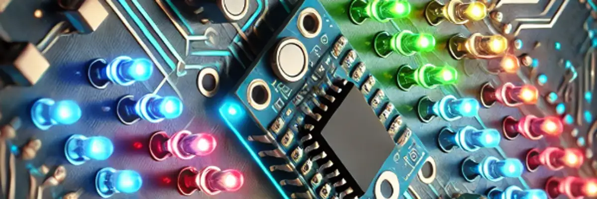
In this project of Attractive Decorative Effects of LEDs using 8051 Microcontroller, you have to connect 8 LEDs to 8 pins of PORT1 of 8051 microcontroller, such that their anodes are connected to respective pins and cathodes are grounded through each resistor of 330 ohms.
Introduction
The 8051 microcontroller is a versatile platform for developing embedded systems. This document provides a detailed explanation of the LED decorative effects program written in both C and Assembly Language Program (ALP). It also explains the procedure for burning these codes onto the 8051 microcontroller.
C Code Explanation
Header File and Definitions
#include <reg51.h>
#include <intrins.h>
#define DELAY_TIME 200
#include <reg51.h>:Includes the register definition file for the 8051 microcontroller, providing access to ports and special function registers (SFRs).#include <intrins.h>:Allows the use of intrinsic functions like rotation operations if needed.#define DELAY_TIME 200:Defines a constant value for delay duration in milliseconds.
Delay Function
void delay_ms(unsigned int ms) {
    unsigned int i, j;
    for (i = 0; i < ms; i++)
        for (j = 0; j < 123; j++);
}
void delay_ms(unsigned int ms):A delay function to create a time gap between LED effects.- Nested loops: Simulate a delay by iterating j 123 times for each ms. The value 123 approximates 1 ms delay.
Main Function
Effect 1: All LEDs on/off
void main() {
    unsigned char i;
    P1 = 0x00;
    while (1) {
        // Effect 1: All LEDs ON/OFF
        P1 = 0xFF;
        delay_ms(DELAY_TIME);
        P1 = 0x00;
        delay_ms(DELAY_TIME);
unsigned char i:Declares a variable to control loops.P1 = 0x00:Initializes Port 1 (P1) to turn all LEDs OFF.while (1):Creates an infinite loop for continuous execution.P1 = 0xFF:Turns all LEDs ON by setting all bits of P1 to 1.P1 = 0x00:Turns all LEDs OFF.
Effect 2: Running LEDs in Both Directions
for (i = 0; i < 8; i++) {
    P1 = 1 << i;
    delay_ms(DELAY_TIME);
}

for (i = 7; i < 8; i--) {
    P1 = 1 << i;
    delay_ms(DELAY_TIME);
}- Left-to-right: Shifts a single LED ON by left-shifting 1.
- Right-to-left: Shifts a single LED ON by decrementing i.
Effect 3: Pair of LEDs Running
for (i = 0; i < 7; i++) {
    P1 = (1 << i) | (1 << (i + 1));
    delay_ms(DELAY_TIME);
}

for (i = 7; i > 0; i--) {
    P1 = (1 << i) | (1 << (i - 1));
    delay_ms(DELAY_TIME);
}- Combines two LEDs by OR-ing two shifted bits.
- Moves pairs left and right.
Effect 4: Chasing LEDs
for (i = 0; i < 8; i++) {
    P1 |= 1 << i;
    delay_ms(DELAY_TIME);
}

P1 = 0x00;- Uses the OR operator to keep previous LEDs ON while turning ON the next one.
Effect 5 and Effect 6: Centered Patterns
for (i = 0; i < 4; i++) {
    P1 = (1 << i) | (1 << (7 - i));
    delay_ms(DELAY_TIME);
}

for (i = 0; i < 4; i++) {
    P1 = (1 << (3 - i)) | (1 << (4 + i));
    delay_ms(DELAY_TIME);
}- Lights up LEDs symmetrically from ends to the center and vice versa.
Assembly Language Program (ALP) Explanation
Initialization
ORG 0000H
MAIN: MOV P1, #00H
      SJMP LOOP
ORG 0000H:Specifies the start address of the program.MOV P1, #00H:Clears all LEDs.- SJMP LOOP: Jumps to the main loop for continuous execution.
Delay Subroutine
DELAY: MOV R7, #200
DLOOP1: MOV R6, #255
DLOOP2: DJNZ R6, DLOOP2
        DJNZ R7, DLOOP1
RET- Uses nested loops with registers R7 and R6 to implement delay.
Effects Implementation
All LEDs ON/OFF
MOV P1, #0FFH
ACALL DELAY
MOV P1, #00H
ACALL DELAY
Running LEDs
MOV R0, #01H
LEFT: MOV P1, R0
      ACALL DELAY
      RL A
      MOV R0, A
      CJNE R0, #80H, LEFT
Chasing LEDs
MOV R0, #01H
CHASE: ORL P1, R0
       ACALL DELAY
       RL A
       MOV R0, A
       CJNE R0, #00H, CHASE
MOV P1, #00H
Similar patterns for other effects.
Procedure to Burn the Code
Burning C Code
- Write and Compile Code.
- Use Keil uVision IDE.
- Create a new project and add the C code.
- Compile to generate a .hex file.
- Flash to Microcontroller:
- Use a programmer like Flash Magic.
- Load the .hex file.
- Connect the programmer to the 8051 board and flash the code.
Burning Assembly Code
- Assemble the code first.
- Use an assembler like ASM51.
- Assemble the ALP code to create a .hex file.
- Flash to Microcontroller:
- Use Flash Magic or equivalent software.
- Follow the same steps as for the C code.
Complete C Code
#include <reg51.h>
#include <intrins.h>
#define DELAY_TIME 200  // Delay time in milliseconds

void delay_ms(unsigned int ms) {
    unsigned int i, j;
    for (i = 0; i < ms; i++)
        for (j = 0; j < 123; j++); // Approximate delay for 1ms
}

void main() {
    unsigned char i;
    P1 = 0x00;  // Initialize Port P1 to all OFF

    while (1) {
        // Effect 1: All LEDs ON/OFF
        P1 = 0xFF; // All LEDs ON
        delay_ms(DELAY_TIME);
        P1 = 0x00; // All LEDs OFF
        delay_ms(DELAY_TIME);

        // Effect 2: LEDs running in both directions
        for (i = 0; i < 8; i++) {
            P1 = 1 << i; // LED running left to right
            delay_ms(DELAY_TIME);
        }
        for (i = 7; i < 8; i--) {
            P1 = 1 << i; // LED running right to left
            delay_ms(DELAY_TIME);
        }

        // Effect 3: Pair of LEDs running in both directions
        for (i = 0; i < 7; i++) {
            P1 = (1 << i) | (1 << (i + 1)); // Two LEDs ON moving right
            delay_ms(DELAY_TIME);
        }
        for (i = 7; i > 0; i--) {
            P1 = (1 << i) | (1 << (i - 1)); // Two LEDs ON moving left
            delay_ms(DELAY_TIME);
        }

        // Effect 4: Chasing LEDs
        for (i = 0; i < 8; i++) {
            P1 |= 1 << i; // LEDs ON cumulatively
            delay_ms(DELAY_TIME);
        }
        P1 = 0x00;

        // Effect 5: LEDs lighting up from ends to center
        for (i = 0; i < 4; i++) {
            P1 = (1 << i) | (1 << (7 - i)); // LEDs ON from ends
            delay_ms(DELAY_TIME);
        }
        P1 = 0x00;

        // Effect 6: LEDs lighting up from center to ends
        for (i = 0; i < 4; i++) {
            P1 = (1 << (3 - i)) | (1 << (4 + i)); // LEDs ON from center
            delay_ms(DELAY_TIME);
        }

        P1 = 0x00;
        // You can add more effects here for creativity...
        // For help comment at the bottom of this post
    }
}
Complete ALP Code
ORG 0000H  ; Program start address
MAIN:       MOV P1, #00H     ; Clear all LEDs
            SJMP LOOP        ; Jump to main loop
; Subroutine for delay

DELAY:      MOV R7, #200     ; Outer loop (adjust for approx. 200ms)
DLOOP1:     MOV R6, #255     ; Inner loop
DLOOP2:     DJNZ R6, DLOOP2  ; Decrement R6
            DJNZ R7, DLOOP1  ; Decrement R7
            RET              ; Return from delay subroutine

; Main loop
LOOP:
            ; Effect 1: All LEDs ON/OFF
            MOV P1, #0FFH    ; All LEDs ON
            ACALL DELAY
            MOV P1, #00H     ; All LEDs OFF
            ACALL DELAY

            ; Effect 2: LEDs running in both directions
            MOV R0, #01H
LEFT:       MOV P1, R0       ; LED moving left to right
            ACALL DELAY
            RL A             ; Rotate left
            MOV R0, A
            CJNE R0, #80H, LEFT

RIGHT:      MOV P1, R0       ; LED moving right to left
            ACALL DELAY
            RR A             ; Rotate right
            MOV R0, A
            CJNE R0, #01H, RIGHT

            ; Effect 3: Pair of LEDs running
            MOV R0, #03H
PAIR_LEFT:  MOV P1, R0       ; Two LEDs ON moving right
            ACALL DELAY
            RL A
            MOV R0, A
            CJNE R0, #C0H, PAIR_LEFT
PAIR_RIGHT: MOV P1, R0       ; Two LEDs ON moving left
            ACALL DELAY
            RR A
            MOV R0, A
            CJNE R0, #03H, PAIR_RIGHT

            ; Effect 4: Chasing LEDs
            MOV R0, #01H
CHASE:      ORL P1, R0       ; LEDs ON cumulatively
            ACALL DELAY
            RL A
            MOV R0, A
            CJNE R0, #00H, CHASE
            MOV P1, #00H     ; Clear LEDs

            ; Effect 5: LEDs lighting up from ends to center
            MOV R0, #81H
CENTER_IN:  MOV P1, R0       ; LEDs ON from ends to center
            ACALL DELAY
            SWAP A           ; Swap nibbles
            ANL A, #7EH      ; Mask center bits
            MOV R0, A
            CJNE R0, #3C, CENTER_IN

            ; Effect 6: LEDs lighting up from center to ends
            MOV R0, #3C
CENTER_OUT: MOV P1, R0       ; LEDs ON from center to ends
            ACALL DELAY
            SWAP A           ; Swap nibbles
            ORL A, #81H      ; Expand outward
            MOV R0, A
            CJNE R0, #FFH, CENTER_OUT

            SJMP LOOP        ; Repeat all effects

END
Conclusion
This document demonstrates how to implement decorative LED effects using 8051 microcontroller in both C and ALP. While C offers simplicity and readability, ALP provides fine-grained control and a deeper understanding of hardware operations. The procedure to burn the code ensures successful execution of the program on the microcontroller. These effects can be extended further for creative applications in embedded systems.


