1. Introduction
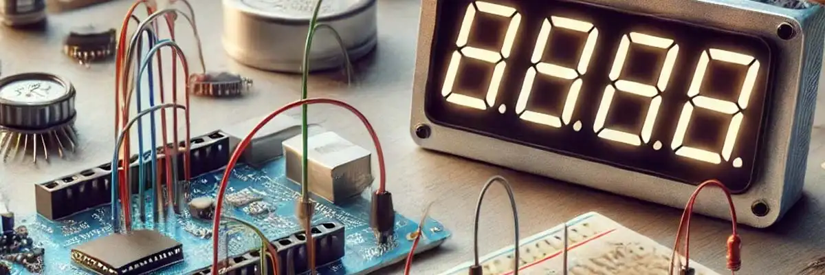
The 7-segment LED display is a simple yet powerful visual output device often used in embedded systems to display numeric data. This project demonstrates how to use a common cathode 7-segment LED display with an 8051 microcontroller (MUC) to create a countdown timer. Upon reaching zero, a connected buzzer beeps five times, and the display then turns off. This setup is a practical demonstration of interfacing components with the 8051, using precise timing, and controlling output devices.
2. Material List and Software List
2.1 Hardware Components
- 8051 Development Board (available well developed board at Vidyasagar Academy)
- Common Cathode 7-Segment LED Display (FND500)
- Buzzer
- 100-ohm, 1W Resistor
- Connecting Wires
- Breadboard (Optional for prototyping)
2.2 Software Tools
- KeiluVision IDE for C programming – check complete guide
- 8051 Assembler for Assembly Language Programming (ALP) or MIDE51 or any assembler (for ALP) – download from this link
- Flash Magic (or equivalent) for programming the microcontroller
3. Details of Common Cathode LED Display (FND500 Type)
The FND500 is a common cathode 7-segment LED display where the common pin connects to ground. Each segment is activated by driving its respective pin HIGH. For instance:
- Pin-a glows when P0^1 is HIGH
- Pin-b glows when P0^2 is HIGH
- And so on…
This configuration simplifies control logic but requires careful wiring. Ensure all unused pins are left open (e.g., P0^0).
4. Details of 8051 MUC
The 8051 microcontroller is an 8-bit controller with the following features relevant to this project:
- Port P0: Open-drain I/O used for driving the display segments
- Port P1: Used for buzzer output
- Built-in timer modules for generating 1-second delays
5. Connection Details with Development Board
5.1 Display Connections
- P0^1: Segment-a
- P0^2: Segment-b
- P0^3: Segment-c
- P0^4: Segment-d
- P0^5: Segment-e
- P0^6: Segment-f
- P0^7: Segment-g
- GROUND terminal: Connected to –ve terminal of the development board through a 100-ohm, 1W resistor.
5.2 Buzzer Connection
- Positive terminal to P1^0
- Negative terminal to GROUND
6. Step-by-Step Code Explanation in C Language
6.1 Initialize ports and variables.
#include <reg51.h>
sbit buzzer = P1^0;

void delay_ms(unsigned int ms) {
    unsigned int i, j;
    for (i = 0; i < ms; i++)
        for (j = 0; j < 1275; j++);
}

void display(unsigned char value) {
    P0 = value;
}
Code Explanation
- sbit buzzer assigns P1^0 to the buzzer.
- delay_ms creates a delay for countdown timing.
- display function outputs values to the 7-segment display.
6.2 Countdown logic
void countdown() {
    unsigned char digits[] = {0xC0, 0xF9, 0xA4, 0xB0, 0x99, 0x92, 0x82, 0xF8, 0x80, 0x90};

    int i;

    for (i = 9; i >= 0; i--) {
        display(digits[i]);
        delay_ms(1000);
    }
}
Code Explanation
- digits array stores the segment codes for numbers 0-9.
- A for loop decrements through the numbers, displaying each for 1 second.
6.3 Logic for Buzzer and Blanking Display
void end_sequence() {
    int i;

    for (i = 0; i < 5; i++) {
        buzzer = 1;
        delay_ms(200);
        buzzer = 0;
        delay_ms(200);
    }

    display(0xFF);  // Turn off display
}

void main() {
    P0 = 0x00;  // Initialize P0
    buzzer = 0; // Initialize buzzer
    countdown();
    end_sequence();
    while (1); // stops everything i.e. code ceases to run
}
Code Explanation
- end_sequence activates the buzzer five times with a delay.
- display(0xFF) turns off the 7-segment display.
7. Complete Code in C
#include <reg51.h>
sbit buzzer = P1^0;

void delay_ms(unsigned int ms) {
    unsigned int i, j;
    for (i = 0; i < ms; i++)
        for (j = 0; j < 1275; j++);
}

void display(unsigned char value) {
    P0 = value;
}

void countdown() {
    unsigned char digits[] = {0xC0, 0xF9, 0xA4, 0xB0, 0x99, 0x92, 0x82, 0xF8, 0x80, 0x90};

    int i;

    for (i = 9; i >= 0; i--) {
        display(digits[i]);
        delay_ms(1000);
    }
}

void end_sequence() {

    int i;

    for (i = 0; i < 5; i++) {
        buzzer = 1;
        delay_ms(200);
        buzzer = 0;
        delay_ms(200);
    }

    display(0xFF);
}

void main() {
    P0 = 0x00;
    buzzer = 0;
    countdown();
    end_sequence();
    while (1);
}
8. Complete Code in ALP
The ALP code is also given for the lovers of ALP. This code is also fully tested in Vidyasagar Academy lab and works perfectly.
ORG 0000H
MOV P0, #0FFH       ; Initialize display off
MOV P1, #00H        ; Initialize buzzer off

COUNTDOWN:
MOV DPTR, #DIGITS   ; Point to digit array
MOV R0, #09H        ; Start count at 9

DISPLAY:

MOV A, @DPTR        ; Load digit to accumulator
MOV P0, A           ; Send to display
ACALL DELAY         ; 1 second delay
INC DPTR            ; Point to next digit
DJNZ R0, DISPLAY    ; Loop until 0

END_SEQUENCE:
MOV R1, #05H        ; Set buzzer beep count

BEEP:
SETB P1.0           ; Turn buzzer on
ACALL SHORT_DELAY
CLR P1.0            ; Turn buzzer off
ACALL SHORT_DELAY
DJNZ R1, BEEP       ; Repeat 5 times
MOV P0, #0FFH       ; Turn off display
SJMP $

DIGITS: DB 0C0H, 0F9H, 0A4H, 0B0H, 099H, 092H, 082H, 0F8H, 080H, 090H

DELAY: ; Delay subroutine
MOV R2, #250
MOV R3, #250

DELAY_LOOP:
DJNZ R3, DELAY_LOOP
DJNZ R2, DELAY_LOOP
RET

SHORT_DELAY:
MOV R2, #100

SHORT_LOOP:
DJNZ R2, SHORT_LOOP
RET

END
9. Applications
- Countdown timers in industrial or educational projects.
- Visual countdown with alarm for exams or interviews.
- Embedded system teaching modules for interfacing components.
10. Conclusion
This project demonstrates the integration of a 7-segment LED display with the 8051 MUC for real-world applications. The detailed explanation of code in both C and ALP enhances understanding and offers flexibility to use either approach. Such projects build essential skills in interfacing and embedded programming.


